Pendulum
Phase Comparator
Monitors Electronic Pendulum Clock
Indicates fine-grain rate drift in near real time.
Read "Electronic Pendulum Driver" for the background on this project.
Max Carter
The Phase Comparator provides a means to electronically compare the beat of the Electronic Pendulum Driver (available at the scope TP) to an external 1 Hz standard. The phase comparator indicates the relative phase of the pendulum's beat, compressing the time required to measure and adjust its rate. Short-term drift can be determined in 15 minutes or less.
Phase Comparator with Reference Source
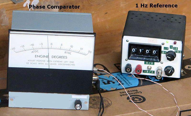
- The 5-inch (127mm) meter and associated circuitry are mounted in an old computer power supply case. The meter was surplus, obviously designed originally for some other application.
- To achieve second-per-week accuracy, the external standard must be accurate to better than one part per million (10-6). (One second/week = 1.6 parts/million.) A quartz-based function generator that has been calibrated against a source traceable to NIST would meet the requirement. It's output level must be 3 volts peak-to-peak or higher. The one shown is calibrated against NIST radio station WWVB. An alternate (better) reference would be a GPS Disciplined Oscillator (GPSDO), like one of these listed on eBay.
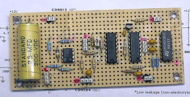
Circuit Board
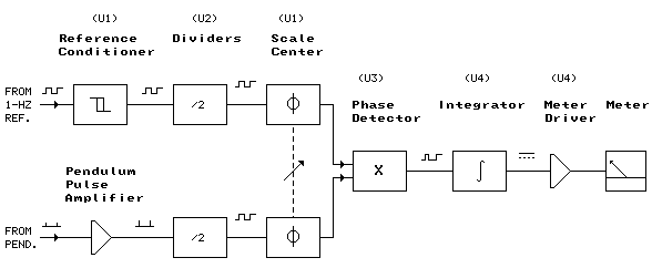
Block Diagram
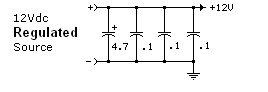
Schematic
Figure 1
 schematic")
|
**The scaling resistor (Rscale) calibrates the meter to 5 volts full-scale at 1 mA. Calculate its value (in ohms) for your (1 mA) meter per the equation: Rscale = 5000 - Rmtr Where Rmtr is the measured resistance of the meter movement in ohms. Other meters can be used. Calculate as follows: Rscale = [5 - (Imtr x Rmtr)] / Imtr Where Imtr is the specified or measured full scale meter current. Or simply use a 5-volt meter (no external resistor needed). |
Scale Calibration
All you really need to know is that full-scale on the meter represents two cumulative cycles or 720 degrees.*
If you want to be more precise, proceed as follows:
If you want to be more precise, proceed as follows:
- Divide the scale into equal major divisions. The easiest way to do this is to simply use the existing scale markings (assuming the scale is linear).
- Convert the number of major divisions (Ndiv) into a fraction (Sfrac) as follows:
Sfrac = 2/Ndiv
- Mark the scale directly or put a sticker on the meter indicating Sfrac per division.
Meter Scale on the As-Built Phase Comparator
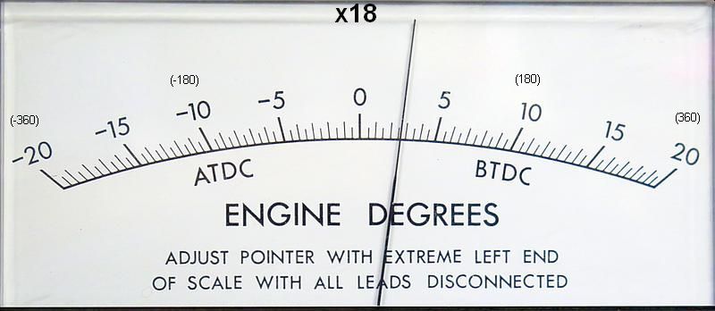
| Sfrac = 0.250 per major division (250 mS at 1 Hz, or 90°) |
*The reading on the scale of this particular meter can be coverted to degrees by multiplying by 18. (47° shown.)
Regulating the Electronic Pendulum Clock
As with all pendulum clocks, regulating the electronically-driven pendulum clock is an iterative process.
- Pre-Adjust
- Pre-adjust the pendulum clock to within a few seconds per hour by other means, such as comparing the clock's second hand to an accurate time source.
- Initialize, Connect and Power-up.
- Set SCALE CENTER control to the center of its range.
- Connect the comparator to the clock motor driver (Scope TP) and external 1 Hz source. Set external source output level to 3Vp-p or higher. Power the comparator.
- Wait for the integrator to settle, about 2 minutes. Adjust the SCALE CENTER control if necessary to obtain an on-scale reading.
Note: The meter responds slowly to the SCALE CENTER control; allow time for it to respond.
- Monitor and Adjust
- Allow the comparator to run long enough to determine if the clock is running fast or slow. A fast-running clock will cause the meter pointer to drift to the right; a slow-running clock will cause the meter pointer to drift to the left. If the pendulum is maladjusted, the meter drift will be noticed within a few minutes. [The clock's rate of drift can be calculated as shown below.]
- If the clock is running fast, tweak the pendulum longer (lower its center of mass). If the clock is running slow, tweak the pendulum shorter (raise its center of mass). The aim is not to produce any particular meter reading, the aim is to produce a stationary meter reading.
- Repeat step 3.
-
Notes:
- As the pendulum comes closer and closer to being on time, the tweaks should become smaller and smaller, becoming very small near the end of the effort. A correctly adjusted pendulum will maintain a stationary meter reading, or very slow drift, for hours.
- Some intra-day variation may be noticed, depending on how the ups and downs of ambient temperature affect the pendulum's length during the day. Monitor the pendulum for 24 hours to allow intra-day variations to average out.
- You may notice the pointer reverse direction and move (relatively) quickly to the opposite end of the scale. This happens when the pendulum drifts out of the meter's ± one-cycle (720°) range, causing a "cycle slip". After the pointer relocates it will resume its previous direction of drift.
- Allow the integrator time to settle after any changes.
"We must not be hasty." - Treebeard
Calculate Drift Rate
Seconds-per-Week and/or Seconds-per-Month
- Adjust SCALE CENTER to a major division mark at or near the center of the scale.
- Monitor the meter and note the number of seconds (Nsec) required for the meter to deflect 1 major division.
- Calculate as follows:
Seconds/week = (Sfrac / Nsec) x 604800
Seconds/month = (Sfrac / Nsec) x 2592000
Remember
- The accuracy of the pendulum phase meter depends on the accuracy of the 1 Hz standard used with the device.
- The meter reads phase; a perfectly timed pendulum will produce a stationary meter reading.
- The meter is sensitive to the slightest deviation from "on-time". If the pendulum is not on-time, it will be noticed in the meter reading within an hour (usually much less than an hour).
- To project long-term performance, monitor the pendulum for 24 hours. This averages out intra-day variations.
Parts
| 2N2222 (PN2222): | Futurlec/PN2222 |
| CD4584B: | Futurlec/CD4584 |
| CD4013B: | Futurlec/CD4013 |
| CD4001B: | Futurlec/CD4001 |
| LF353N: | Futurlec/LF353 |
| Resistors, capacitors: | Futurlec/components |
| Panel meter, 1 mA: | ebay, etc. |
| GPS Disciplined Oscillator | ebay/GPSDO |
Futurlec is cheap, but they're slow. Allow 2-3 weeks for delivery.
Related Pages
Electronic Pendulum Driver
Computer Interface
WWVB
More GPSDO
GPSDO Drives Electro-Mechanical (Analog) Clock
|
|
 |
Schematics produced with DCCAD.
