GPS-Disciplined Oscillator

GPSDO Drives Electro-Mechanical (Analog) Clock

Circuit converts unipolar GPSDO output to bipolar clock motor drive signal.

Max Carter


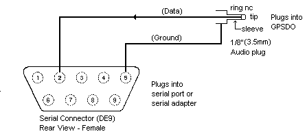
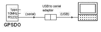
A GPS-disciplined oscillator (GPSDO) provides precisely timed 100 mS unipolar (3.3V) pulses at one-second intervals (1 pps), synchronised to Coordinated Universal Time (UTC). A GPSDO can be had for around $100 from eBay.

The pulses can be used to synchronize an ordinary $10 battery-powered (minus the battery) clock movement. Two circuits are shown. Figure 2 supports 1 pps, non-continuous sweep (stepped) movements, Figure 3 supports continuous sweep movements.

Figure 1

Figure 2
(stepped movement)

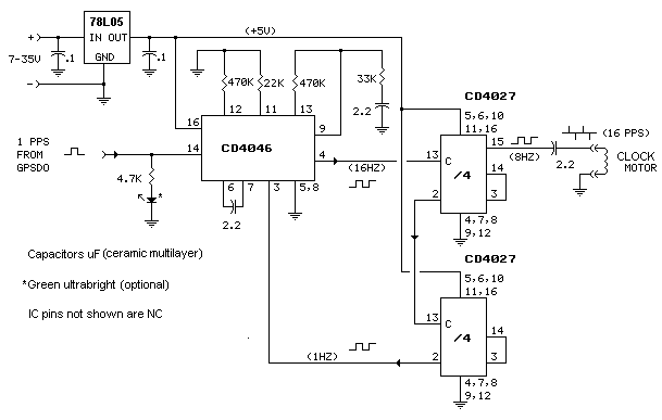
The input pulses from the GPSDO drive a CMOS CD4027 dual flip-flop (only one section of which is used). The flip-flop delivers a symetrical 0.5 Hz square wave to the half-bridge driver circuit made of complementary (PNP/NPN) transistors. The output from the half-bridge is coupled to the clock motor through the 220 uF coupling capacitor. The capacitor value was selected to deliver alternating (positive/negative) 50 mS pulses to the clock motor.* The circuit requires positive DC power in the range of 7-35 volts. It can be powered from the same source (wall wart) that powers the GPSDO.
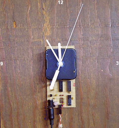
*Motor Coupling Capacitor

The value for the coupling capacitor is derived from the equation

C = T/R, where T is the width of the motivating pulses and R is the resistance of the motor winding.

  • A typical stepped movement will want to see pulses of around 50 mS and the motor winding will have a resistance of around 220 ohms. The calculation becomes .05/220 = .000227 F (227 µF).

  • A typical continuous sweep movement (see below) will want to see pulses of around 10 mS and the motor winding will have a resistance of around 4000 ohms. The calculation becomes .01/4000 = .0000025 F (2.5 µF).
These motors are fairly forgiving, so it's likely the values shown in the schematics will work with any movement of the same type.

As Built


Clock Modification - Connecting to the Motor Winding

  • Disassemble the clock to gain access to the solder pads on the circuit board where the motor winding is connected. Be sure to note the order in which the wheels (gears) are removed.
  • Using a utility knife or small hand grinder, cut one of the traces on the circuit board so as to isolate the winding from the on-board circuitry.
  • Tack solder a length of AWG 28 (.08mm2) two-conductor wire to the pads.
  • Route the wire to the outside of the motor case.
  • Reassemble the clock. (It's not necessary to reinstall the battery.)
  • Reinstall all hands pointing at 12. Verify the hands are parallel and not touching. Do not reinstall the plastic face cover (if there is one).

Initialization

Initialization is done manually. Go to Official U.S. Time or other UTC source. With the clock running, move the minute and/or second hand as necessary until the clock displays the correct time. Do not force the hour hand. The clock will continue to tell the correct time unless power is interrupted.

Installed

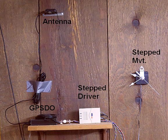
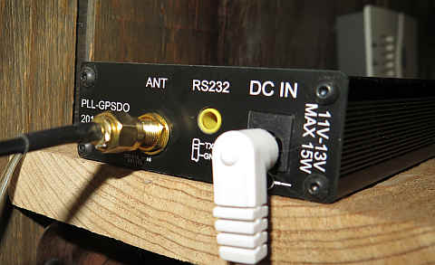
The GPSDO is on the left. The converter/driver is in the white plastic box on the right.


Alternate Motor Driver

Circuit Accommodates Sweep-Style Movement

Most bare quartz clock movements available today for repair or DIY are of the "sweep" persuasion. Rather than moving in one-second steps, the second hand moves continuously and steadily. This circuit converts the 1 pulse per second output from the GPSDO to a 8 Hz AC drive signal to spin the clock's two-pole motor at 8 revolutions per second (480 RPM). The movement's gear train reduces the 480 RPM motor speed to 1 RPM second hand speed.

Figure 3
(sweep movement)

The heart of the circuit is a CD4046 CMOS phase-locked loop. The 16 Hz output from the 4046's voltage controlled oscillator (VCO) is divided by 16 through a couple of CMOS CD4027 dual JK flip-flops and fed back to the 4046 where it is phase-compared to the 1 Hz reference from the GPSDO. The voltage output from the phase comparator corrects the VCO frequency to precisely 16 Hz. The first CD4027 stage provides symetrical 8 Hz drive to the clock motor. The impedance of the motor winding is high enough that it can be driven directly by the CMOS CD4027. back

As Built


Play Video

Follow the instructions above for clock modification. Initialization is the same as above except the sweep second hand should only be moved manually in the clockwise direction.


Addendum

Other Available GPSDO Outputs

A precise 10 MHz frequency reference output is also provided, useful for frequency calibration, along with a serial RS232 9600 BPS NMEA signal for use with GPS geolocation software. Neither of these outputs are used in the above clock applications but are always available.

  • The serial interface on this GPSDO is a 3.5mm tip/ring/sleeve audio jack on the rear panel.

    Use an adapter like the one shown below (from Amazon):

    DE9 9 Pin Female to 3.5mm Male Plug

    Or roll your own:

    Figure 4


  • Serial (RS232) COM ports have disappeared from desktop and laptop/notebook computers, but a serial COM port is easily provided using a serial adapter. The cable from the adapter plugs into a USB port on the computer. The adapter shows up as a COM port in Device Manager (control panel|device manager), typically COM5. This one is from Amazon.

    USB to Serial Adapter

    Figure 5

  • Some GPSDOs are equipped with a USB interface, eliminating the need for the serial adapter. These will also show up as a COM port in Device Manager, probably COM5.
  • Data can be checked with a terminal program such as Termite. Settings: COM5 (or whatever), 9600 BPS, 8N2, no handshake. Disconnect the terminal program before starting your geolocation program.

Schematics produced with DCCAD.


Related Links

A GPSDO can be had for around $100 from eBay

Official U.S. Time

Geolocation/Time Sync Software

DE9 9 Pin Female to 3.5mm Male Plug

USB to serial adapter

Termite


Another GPSDO Application

Pendulum Phase Comparator


cat