A 200-Watt Push-Pull Class-E AM Transmitter for 1710 kHzMax Carter
find on this page | xmtr photos | calculators | directional wattmeter | antenna photos | comments This transmitter is based, more or less, on equations presented in a 1988 Mark Mallory article detailing a single-ended class-E output stage for a 1-watt transmitter operating in the 160-190 kHz Part-15 LowFER band. The present circuit is a push-pull design and achieves about 93% efficiency at 1710 kHz. The circuit should be adaptable to transmitting in the 160-meter ham band with slight component value changes, or to any frequency within the medium or longwave bands (0-2 MHz) by following the design steps below. The 'as-built' transmitter can be tuned about 100 kHz either side of 1710 kHz (1600-1800 kHz) without modification.
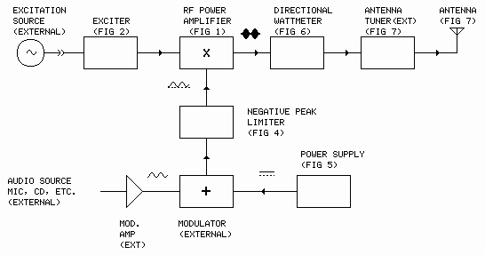
The transmitter has the same basic layout as any AM transmitter, though it may differ in specifics. A block diagram of the as-built unit appears below. Refer back to this diagram as the parts are explained in the article below. Items marked "external" are not described (except in a general way) in the article. |
|
The transmitter's output amplifier circuit is shown in Figure 1: |

|
The amplifier circuit consists of two of the Mallory circuits connected in a push-pull configuration with a coupling transformer acting as both the finals' tank inductance and output matching device. The push-pull configuration allows current sharing between two transistors while the transformer provides great flexibility in matching the amplifier to a load. The push-pull configuration also greatly reduces the second harmonic content of the output signal, lowering the demands on the output filtering. The .0055 uF value for the capacitors tied to ground at the ends of the output transformer primary was determined from Mallory's equations, as was the inductance of the transformer primary. The number of turns specified for the transformer primary winding was determined from the winding chart for the specified core. The output power of Mallory's 1988 prototype was adjusted by selecting an appropriate tap on the final tank inductor. In a similar manner, the output power of the present unit (at the specified power supply voltage) is determined by the primary/secondary turns ratio of the output transformer. The 8-to-18 turns ratio shown on the schematic was selected to take full advantage of the current available from the power supply. To state it another way, the ratio shown adapts the final-stage 11-ohm output impedance to the unit's 50-ohm output feedline (load) impedance. The output filter consists of the output coupling capacitor C2 and series inductor L1. This type filter satisfies the basic requirement for class-E operation: The final 'sees' the output load at the fundamental frequency only. Higher order harmonics are blocked and the filter presents a high impedance back to the amplifier stage at those frequencies. The output filter has a Q of 5. The IRFP350LC MOSFETs in the final are low gate charge types (the 'LC' in the part number). This type has a reduced gate drive power requirement compared to 'standard' types. Additionally, class-E operation substantially cancels the 'Miller effect', a dynamic interaction between the FETs' drains and gates caused by inter-electrode capacitances, further reducing the drive power requirement. Adjustment of the 750 pF variable capacitor (C1) across the primary (between the drains of the output transistors), along with SYM and BAL adjustments in the exciter, serve to fine tune the transformer primary to achieve optimal class-E operation. After adjustment, two watts of drive power easily drives the final stage to its full 200-watt output. The output transistors are mounted on a 5.5"x5"x1" aluminum heatsink. A small fan circulates air across the heatsink. The driver transistors are mounted on a small board mounted directly on the output transistor leads. The push-pull drive signal for the power amplifier is developed by the exciter circuitry shown in Figure 2. This circuit's adjustability is the key to obtaining optimal efficiency of the class-E output stage: |
(as-built)

An input signal must be provided to this
circuit from a signal generator, crystal oscillator, VFO or other source
at TWICE the operating frequency, 3420 kHz in the case of the as-built
transmitter. (The carrier source for the as-built unit is a programmable
synthesizer.) The CD4013 flip-flop divides the input signal by 2 and
delivers 'perfect' 50% duty-cycle drive signals to the exciter output
gates. A ground on the standby/operate input at the bottom of the circuit
enables the output gates. A telegraph key could be connected at this point
for CW code operation. The DELAY BAL and SYM controls are adjusted during
tune-up to optimize operation of the transmitter's driver and output
stages. The drive signals are buffered and delivered to the driver
transistors via short lengths of shielded wire.
ConstructionIf you'd like to reproduce this transmitter, the components and values shown should work as advertised at 1710 kHz using a 42-volt power supply. Fixed capacitors should be mica dielectric or low ESR type where indicated; the values shown can be made up with smaller-value units in parallel. C2 should be a transmitting type air or vacuum variable. The output transformer primary windings should be made with AWG 16 or heavier wire. The secondary should be of AWG 18 or heavier. Cores other than the one shown (the biggest one I could find) can be used with the number of primary turns recalculated (see below). The core material should be type-2 powdered iron. The output transistors should be mounted to the heatsink with insulating hardware. The heatsink should be grounded. A 160m version of the 200-watt transmitter can be built by following the schematic in all respects except for the following change: substitute .0044 uF capacitors for the .0055 uF units shown at the ends of the output transformer primary winding. If you'd like to try the circuit at other frequencies or power levels, first carefully read the Mallory article, then decide at what frequency you'd like the transmitter to operate (usually in the range from 10 kHz to 2 MHz; see frequency below), at what power level (taking into account the available power supply voltage and current), and the required output load impedance (typically 50 ohms), then:
Tune-up:
The transmitter's final current ammeter and voltmeter should be used
to check for proper loading on the output stage. The supply voltage
divided by the current should equal about 80% of the load impedance
calculated in design step 3 above (11 ohms for the as-built transmitter).
Thus, for the unit's 42-volt power supply, the correct DC current is about
5.25 amps [42/(.8x10)=5.25]. Output power is calculated as follows: The transmitter is tolerant of reactive (high VSWR) loads. Mismatches can be tuned out by adjusting the output coupling capacitor (C2). However, depending on the nature of the mismatch, the transmitter may not deliver the calculated output power in that situation. Remember that the transmitter's output power is limited only by the capability of the power supply. If the non-reactive (resistive) component of the load impedance is less than the amplifier's design load impedance, the amplifier will dutifully try to deliver the extra current, possibly overheating the power supply. If the load's non-reactive component is greater than the design impedance, the output power will be less than calculated. As mentioned, the amplifier can be designed to operate into almost any load impedance - refer back to construction step 3 above - but employing an external tuner, like the one shown in Figure 7 below, is usually a more practical approach to unusual or unknown impedance situations. Pushing the LimitsPower: The T-400-2 core shown should be capable of power levels up to a couple of kilowatts, but if your design calls for more power, stack multiple cores for higher current capability. Stacking of cores will require recalculating primary turns per the cores' winding chart. Add the AL values when stacking cores. For example, stacking 2 cores, each with an AL value of 185, will result in a total AL value of 370. The output transformer should be wound with wire heavy enough to carry the expected current with minimal heating loss, as should inductor L1. Output coupling capacitor C2 likewise should be sized to handle the expected current and voltage. Consider using a vacuum variable for C2.
Frequency: ModulationThe as-built transmitter is amplitude modulated by an external 8-ohm transformer-coupled audio power amplifier, salvaged from a public-address system, connected through the modulation input terminals shown in Figure 1. Audio amplifiers, tube or solid-state, meant for public-address service are ideal in this application since they are almost always of transformer-coupled output design. Before connecting the modulator to the transmitter, a check should be made with an ohmmeter to make sure the output winding of the modulation amplifier is floating (i.e., not connected to ground). If there is a ground connection, it should be removed. Connect the terminal from which the ground connection was removed to the positive terminal of the power supply (Fig 3, Opt 1). It may be easier to isolate the negative terminal of the power supply, in which case the modulator would be connected between the negative terminal of the power supply and ground (Fig 3, Opt 2). A modern solid-state linear (class-AB) or class-D audio power amplifier, perhaps meant for use in a high-fidelity home audio system or high-powered car stereo, can also be used as a modulator, but the amplifier output terminals must (1) be isolated from ground and (2) have very low terminal-to-terminal DC resistance (<0.5 ohm). If a check with an ohmmeter reveals that both of these conditions are met, the candidate amplifier can be connected directly to the transmitter modulation input terminals shown in Figure 1, otherwise it must be coupled to the transmitter through a transformer. A 500-watt 120/120VAC isolation transformer is nearly ideal for this (Fig 3, Opt 3). Note that the modulation transformer, be it the modulation amplifier's output transformer or the isolation/coupling transformer mentioned above, represents a DC resistance in series with the power supply and will thus subtract from the voltage presented to the final amplifier. For example, 5 amps through a 0.5-ohm transformer winding would produce a drop of 2.5 volts. Fortunately, an amplifier sufficiently rated to fully modulate the transmitter typically will have an output winding resistance low enough to produce negligible voltage drop. The output winding of the PA amplifier used with the as-built transmitter measures about 0.25 ohms.
An alternate method for coupling the modulation amplifier to the transmitter is shown in Figure 5 below. Called 'modified Heising', this method does not require a floating, low-resistance amplifier output - and thus no transformer! - but works only with the specific type of power supply shown in Figure 5. The options for connecting a modulation amplifier to the transmitter are summarized in Figure 3. |


|
Notes to #4
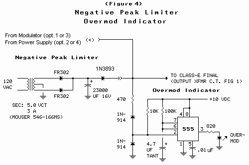
Modulator Power: As with any AM transmitter, in order to achieve 100% modulation, the modulation amplifier must be capable of RMS audio output power half that of the final RF amplifier's steady-state DC input power, and a peak (instantaneous) audio output power twice that value. Thus the as-built transmitter requires 110 watts RMS and/or 440 watts peak audio power from the modulation amplifier. The peak power specification is the more important of the two in determining if an amplifier is suitable for AM service at a given power level. Often the RMS power rating of an audio amplifier does not reflect the amplifier's true available peak power (which should be 4 times the RMS rating). The commercial PA amplifier used to modulate the as-built transmitter, for example, is name-plate rated at 150 watts RMS, but peaks at about 500 watts. While the amplifier will in fact deliver 150 watts as measured with a true RMS voltmeter, at the 150-watt level the output is distorted (clipped). The manufacturer has fudged the RMS rating. The "honest" RMS rating would be 125 watts. Still, the amplifier is adequate for the purpose of modulating the 200-watt transmitter. Modulator Voltage: The test for amplifier suitability can also be stated in terms of voltage as follows: Peak-to-peak modulation (modulator output) voltage under equivalent load must be equal to or greater than twice the transmitter's power supply voltage. [Find "equivalent load" by dividing the RF amplifier's final stage DC power supply voltage by the current drawn by the final. For example, the described transmitter's power supply voltage is 42V; the current drawn by the final is 5.25A. 42 divided by 5.25 yields 8 ohms.] The stereo amplifier bridging conections shown in the box below can be useful in the effort to generate sufficient modulation voltage. The schemes effectively double available amplifier output voltage. Negative Peak Limiting: The modulation envelope can be monitored with an oscilloscope connected to TP1 (sweep speed set to 1 mS per division). Over-modulation will be noted as a flatlining or pinchoff of carrier power at the envelope minimum. Pinchoff occurs when negative modulation peaks exceed the power supply voltage. At that point the instantaneous drain voltage on the output transistors drops to zero (or lower), causing instantaneous output power to drop to zero. Over-modulation produces distortion in the transmitted audio and wide-band splattering of the transmitted signal. Also, driving the drains of the output transistors negative will cause the MOSFETs' internal zener diodes to conduct in the forward direction, possibly causing failure of the output transistors. Ideally, the modulation amplifier should be intrinsically incapable of delivering a voltage spike greater than what is needed for 100% modulation, but practically the modulator will need to be limited in some way, either in the audio stages ahead of the modulator's power amplifier or between the power amplifier and the transmitter. Over-modulation can be avoided with the indicator and negative peak limiter circuits shown in Figure 4. The circuits are independent and each can be used with or without the other. The circuit(s) are placed between the (+) modulator output (Figure 1 connection), or the power supply output (Figure 5 connection), and the center tap of the transmitter output transformer. |
|
The negative peak limiter circuit consists of a 3-volt DC power supply connected to the positive modulation input terminal through a fast-recovery, high-current rectifier diode. The diode is reverse biased under normal conditions (mod input <100%). When the input voltage drops below about 2 volts, the diode conducts and supplies current to the transmitter to maintain a minimal carrier output level. Also, some of the current supplied during negative peaks is forced back into the energy storage capacitors in the main power supply, causing a slight increase in power supply voltage and subsequent increase in average carrier output power. The circuit eliminates splattering and reduces (but does not eliminate) audio distortion. The over-mod indicator functions whenever the input voltage drops below about 2.5 volts. At this point the 555 timer is triggered and lights the LED (mounted in the transmitter's front panel). The LED will stay lit for about one-half second for each excursion of the input voltage below the trigger point. The timer will be retriggered on each input excursion and continuous over-modulation will produce a continously lit LED. Series Modulation: A series-type pulse-width modulator (PWM) can also be used to modulate the transmitter. In that case, since the modulation power is derived from the transmitter's power supply, attention must be paid during the transmitter's design phase to issues like power supply voltage and current, as well as output stage impedance, to properly incorporate the series modulator in the overall transmitter design. As a general rule, for a given output power (full-carrier double-sideband) using a series modulator, the power supply voltage is specified at twice that required for CW service at the same power level and impedance, with a current capability about 150% of the CW rating. Additionally, the power supply should be capable of delivering a current surge equal to or greater than 200% of the current required for CW service. (The 200% surge requirement applies to any AM transmitter's power supply; see the power supply addendum below.) To series modulate the as-built 220-watt transmitter, for example, would require a power supply continuously rated for 84 volts at about 8 amps (10.5 amps surge). Design calculations are applied at the chosen CW operating voltage or idle point, the voltage the transmitter operates at with no audio input. For a series modulator adjusted to idle midway between the power supply voltage and ground (full-carrier double-sideband), the design calculations are made at 1/2 the power supply voltage, or 42 volts for the as-built, Fig-1 version of the transmitter. One of several advantages of series modulation is that the modulator is incapable of negative over-modulation, i.e., driving the drain voltage on the transmitter's MOSFETs into negative territory (<0). Conversely, positive modulation is limited only by the voltage and current capability of the transmitter's power supply. These attributes can be used to generate several variations of AM: full-carrier double-sideband, "super-modulated" AM and reduced-carrier double-sideband. Shorting Jumper: A shorting jumper should be placed across the modulation input terminals in Figure 1 (and/or Figure 5) to operate the transmitter when a modulator is not attached. 100% Modulation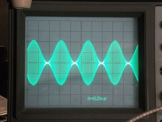 Power SupplyThe 42-volt/5.25-amp. power supply used in the as-built 200-watt class-E transmitter is shown in Figure 5. Constructed entirely of surplus parts, it's very well behaved and operates effortlessly. |

|
In order to acheive 100% modulation, an AM transmitter's power supply must be capable of providing, on a short-term basis, twice the current required during steady-state (CW) operation, 10.5 amps in this case. The supply in Fig. 5 uses inductive and capacitive energy storage to provide a relatively stable output voltage during and between modulation peaks. The filter/energy storage network that follows the rectifier also takes full advantage of the transformer secondary's available voltage and current (ie, high power factor) without excessive component warming. The military surplus transformer used in the as-built supply appears to be under-rated by about 20% in the circuit. While the as-built power supply is well matched to the task of powering the transmitter, almost any power supply design with a full-time steady-state rating sufficient to acheive the desired CW output level can be used. A grossly over-rated supply should be avoided, however. The power supply should be electronically regulated or intrinsically current-limited to 150-200% of calculated transmitter final input current. (The supply in Fig 5 is intrinsically limited, due, apparently, to the high-impedance (%Z) design of the transformer.) The power supply should be provided with a slow-blow fuse sized at about 150% of transmitter DC input power WattmeterA directional wattmeter is installed in the as-built transmitter. The circuit is shown in Fig 6: |
as-built

|
The AD835 4-quadrant multiplier is connected as a voltage adder and squaring detector. A scaled current sample, derived from a current transformer (photo) connected in series with the transmitter's output (converted to a voltage by the 10-ohm shunt resistor), is delivered to pins 8 and 1. A scaled voltage sample, picked off at the transmitter's output connector, is delivered to pins 7 and 2. The chip adds and multiplies the two signals, producing current flow (DC) in the meter directly proportional to the power flow in the transmitter's output circuit. A switch is provided to reverse the phase of the current sample, allowing power flow reflected from the load to be read. True (real) power delivered to the load is the difference between the forward and reflected readings. Addendum: AntennaReaders may be interested in the antenna system used with the as-built 1710 kHz transmitter. The schematic is shown in Figure 7. |

|
The antenna system consists of three parts: 1) the radiating element, 2) the grounding system, sometimes called the counterpoise, and 3) the transmisson line/matching network. During planning and construction of the antenna, these general guidelines were followed:
The transmission line is type RG-8 (though smaller RG-58 would probably work nearly as well if the run is short), the roller inductor is a silver-plated type (almost all are) and the capacitor is a transmitting-type air variable (photo). The matching network component values shown in Figure 7 should be usable over a fairly wide range of radiating element lengths. Optimal adjustment of the as-built antenna occurs with the tuning capacitor about half meshed and the roller inductor tap located about midway on the roller coil. Longer radiating element lengths require less inductance and more capacitance; shorter lengths require more inductance and less capacitance. Would-be builders of a transmitting antenna for 1710 kHz need not follow the particulars of the circuit in Figure 7, however, the guidelines should be followed. The challenge will be to radiate as much of the transmitter's output power as possible so as to produce the strongest on-air signal possible. A random length of wire connected to the transmitter's output connector will not acheive that goal. Building and tuning the 200-Watt Push-Pull Class-E AM Transmitter should be relatively hassle-free for an experienced constructor as long as the design steps and construction notes are followed. The builder should also expect and be willing to expend equal time and energy constructing and tuning the antenna. Schematics produced with DCCAD. |
Comments/Questions:Latest comments are at the bottom of the file. ↓ Top of page. ↑ [Sat Oct 29 11:44:26 2005] about.... Hi Max,I enjoyed reading about the AM transmitter project - the push-pull topology is what I used for mine except I used IRF620's and was about 10dB down on your for output power! I used fet driver chips with a transformer to force a square wave on the gates. I am curious about your use of the 2N2222 as the complimentary drive - was it really happily driving those big fat (1200pf or so input) fets at nearly 2megs!!??I am wondering if I ought to give it a go as I have a 9100b Optimod AM broadcast audio processor....it would be fun to join in the 160M phone nets using something like that!Kind Regards,Rash. [748] [Sat Oct 29 11:44:26 2005] classe... Thanks for the nice comment, Rash. Yeah, the drivers seem happy. As mentioned in the article, class-e operation reduces the gate drive requirement. After adjustment, the two driver stages together draw about 175 mA at 10 volts. Max [199] [Tue Jun 27 07:10:05 2006] classe... HI!ABOUT MODULATION,CAN I USE PWM OR CLASS H MODULATOR? [71] [Wed Jun 28 03:46:08 2006] classe... Yes. Max [148] [Tue Jul 4 04:16:55 2006] classe... please I'm a nigeria undergraduate in one of nigeria universities,i'm PHILIP, i want to learn how to design a transmitter.can i learn from your company. [219] [Sun Jul 30 10:04:08 2006] home..... Hi!how is the rms power of 1710khz trans. and how is the pep?thanks! [111] [Sun Jul 30 10:06:45 2006] home..... Hi!how is the rms power of 1710khz trans. and how is the pep?thanks!Can i tune this transmitter 550-1800khz? [153] [Sun Oct 22 04:28:16 2006] catradio. Radio QRP - The Art of Low Power and Clandestine Operationshttp://www.geocities.com/Radio_QRP/We need your support! QRP is The Art of Low Power Radio where the challenge is to operate and/or build AM radio transmitters using a bare minimum of components, money and construction skill. Why work QRO with a factory set, when homebrew QRP works really well! We are searchin for the ultimate design of a Grenade transmitter or Grenade Clone with a minimum of 5-10 watt output and is complete and working! Can anyone help us locate such a unit? We would appreciate any ideas on how to design this rig. Information in this subject would be appreciated! Thanks! [754] g [Sun Jun 24 10:14:35 2007] classe... hi MAX i m alex from greece . I am an amateur in AM BAND. 1600KHZ. I have an am pll exciter about 30watt output.I Want to help me on a linear amplifier about 250-300watt. do you have any circuit about this?? [258] [Sun Jul 1 19:35:23 2007] classe... This is an extremely well produceddocument, well done and thanks.I have not used a push pull pa beforebut intend to have a go, using yourdata.best regards Finbar [217] [Mon Aug 27 22:46:48 2007] classe... Hi Max. My name is Agus. I m enjoying as a ham since 1979 when i was in middle school. I am intersesting in class e project and i found in the net your very clear project page. I m reproducing your schematic for 80 mtr band and it works at least i can produce RF. My problem is the power output is only 120 Watt.By knowing my problem i came back to see wheter i m overlooking something.Could you share your experience about my problem? Thanks for your help. Thanks Max 73s fer u es family. [588] [Wed Jan 16 17:48:02 2008] classe... Nice page. I just got done building a 50 watt AM transmitter a little while ago using a mosfet. I don't think the design counts as true class E but it puts out a clean good signal. I find mosfets are the best way to build larger lower frequency transmitters today from longwave up to 3 or 4MHz. If your interested here's my design.. (note it was kind of a makeshift rig and was my first ;)... http://i92.photobucket.com/albums/l12/defectivemachine/AMTXfinal.jpg Anywho check out our message board at.. http://darkliferadio.proboards100.com [615] [Tue Mar 11 12:15:40 2008] home..... Nice site. A good couple of hours entertainment. (Make yourself the PDM modulator! You'll love it!) FFFR, Andy [154] [Mon Mar 17 04:49:15 2008] viewcoms. Thank you Andy, Actually, I tried for several months to get the PDM to work.. without success. So I went back to using iron.. Max [170] [Mon Mar 24 21:29:26 2008] classe... Lo felicito por su excelente descripci��n del amplificador Clase E de 200 vatios. E realizado una sabana electr��nica en Excel, que me gustar��a enviarle, donde desarrollo las sencillas formulas de Mark Mallory. Entrando los valores del ejemplo de Mallory, da los valores esperados. Entrando los valores de su amplificador, algunos no me coinciden y me gustar��a conocer su opini��n al respecto. La resistencia de carga en mis c��lculos es de 22.2 �� y usted habla de 10 �� en su circuito El condensador del tanque me da 2.433 pF y usted coloca 5.500 pF ( 0.0055 uF) Me gustar��a saber su correo para enviarle dicha sabana de Excel Atentamente, Herbert Botero B. antecol@une.net.co [828] [Tue Mar 25 09:34:04 2008] viewcoms. Thanks for the nice comment, Herbert. I went back and recalculated the inductor and capacitor values for the 1.71 MHz class-e AM transmitter and discovered an error in the design instructions given in the web article. The confusion comes from the fact that the 1.71 MHz circuit is a push-pull design, whereas the Mallory circuit is single-ended. The error (my error) is in the P (power) term in the first equation (calculating for L). Since the power is shared by two tank circuits, the P term in the first equation should be 1/2 the output power. I did not make that clear. I have re-written steps 1, 2 and 5 to clarify the design procedure. Please retry it - use 200 watts for P. Here are the results of my calculations: Calculated L = 1.07 uH AL value (for T400-2 core, from table) = 185 Calculated turns (on T400-2 core) = 7.6 (rounded to 8) Calculated C = 4829 pF (I used 5500; I happened to have ten 1100 pF mica caps on hand) Calculated Z = 11 Ω (approx. 10) I don't have contact information for Mark Mallory. If you like, you can send the spreadsheet file to me as an email attachment. Sorry for the confusion. Regards, Max [13] [Thu Mar 27 05:17:54 2008] viewcoms. As a result of the above exchange, I put a CALCULATOR on the class-e equations page. Click: /classexmtr/classecalc.html Max [13] [Thu May 1 08:29:22 2008] classe... RF POWER LINEAR AMPLIFIER [35] [Fri May 2 08:46:05 2008] viewcoms. Class-e definitely ain't linear! Max [61] [Fri May 16 05:48:42 2008] amblog... BLOCK DIAGRAM EN FUNCTIONS OF EACH BLOCK [50] [Thu Jun 5 14:08:53 2008] classe... sir, you are not giving audio in put stage clearly please give this through email illiraj55@yahoo.com thanku for yours corcut idea [158] [Thu Jun 5 14:12:46 2008] classe... give a simpul shmatric of am tramsmitter with long range i think you used mpspet hi watt with parell more than above and increase the range of trannsmitter and watt also [185] [Fri Jun 6 07:22:23 2008] classe... illiraj55@yahoo.com, The [class-e AM transmitter] article shows the transmitter circuitry and gives some suggestions for interfacing a modulation amplifier. (The audio modulation power is supplied by the modulation amplifier.) As suggested by the article, many commonly available amplifiers, tube or solid-state, can be used - public address, home audio, car stereo, etc. The details of the modulation amplifier are beyond the scope of the article. Max [476] [Fri Jun 6 08:36:06 2008] viewcoms. I've never had very good luck paralleling MOSFETS. Must be doin' somethin' wrong.. Max [112] [Tue Jun 17 14:30:08 2008] viewcoms. give simpul hi watt long range transmitter you are not giving smematric about 200w transmitte give simpul ababul productto make simpul [160] [Tue Jun 17 14:47:19 2008] viewcoms. sorry sir, parallel mospet means in rf out put stae we used pus pul type two mospet and increase this range through increase the pear of mospet like two pear & 3pear and increase volteg like (ups or invertor) circut .and increase the range thanku for reading and ancer me (112) illiraj55 [335] [Wed Jun 18 09:47:42 2008] viewcoms. Here's a block diagram of the class-e AM transmitter (about the same as any other AM transmitter). Note that items marked "external" are not described (except in a general way) in the article:  Hope this is helpful. Max [243] [Wed Jun 18 10:14:00 2008] viewcoms. illiraj55, Yeah, I know that in theory one can parallel MOSFETs to increase the power handling ability of the stage. I just have never had any luck doing it at the frequencies and modes (class-e) that I've tried.. Max [259] [Fri Jun 20 12:56:58 2008] home..... sir what is class e type transmitter and other a,b,c type transmitter illiraj55 [131][-1][-1] [Fri Jun 20 14:09:04 2008] viewcoms. illiraj55, Class A - output MOSFET (or other device, i.e., bipolar transistor or tube) conducts during 100% of the RF cycle time, Class B - output device conducts 50% of the RF cycle time, Class C - output device conducts less than 50% of the RF cycle time (typically about 45%), Class E - output MOSFET acts as a switch, conducts only when the drain voltage is at 0. This is usually around 50% of the RF cycle time, but can vary depending on circuit parameters. Look on the internet for further explanation of the various "classes". Wikipedia is usually pretty good. Max [685] [Mon Jun 23 12:43:37 2008] viewcoms. sir , still ihave adout 3.42 mhz carrier source means ?where i get this get idea details thanku for ancer me illiraj55@yahoo.com [184] [Tue Jun 24 06:08:30 2008] viewcoms. illiraj55, Quoting the article: "...a signal generator, crystal oscillator, VFO or other source.." This would probably work:  In looking at this it occurred to me that a commonly available 3.58 MHz "colorburst" crystal should work in this circuit, for an operating frequency of 1790 kHz or thereabouts. Max [181] [Wed Jun 25 00:17:40 2008] viewcoms. THANKU SIR ILLIRAJ [44] [Thu Jun 26 12:06:58 2008] viewcoms. max i have a 500w/1kw transmitter circut can you give idea to make simpul this ai 1.9mb give your email add i give you this thanku illiraj55@yahoo.com [202] [Thu Jun 26 13:17:29 2008] viewcoms. Illiraj, I emailed you regarding this. Check your email. Your choice. Max [148] [Thu Jun 26 23:52:22 2008] classe... RF POWER AMPLIFIER DRIVER [35] [Fri Jun 27 06:46:19 2008] viewcoms. You might try phrasing your comment as a complete sentence.. Max [88] [Fri Jun 27 11:55:49 2008] viewcoms. sir, i sent this circut diagram through uplod option but it not give finish command after sending it will be heng up so if you are not receive than sent me e mail clearly my e mail illiraj55@yahoo.com and write (max) also then i understand uoy know there is more adv mels are comming and confus the peapul thanku sir [342] [Sat Jun 28 15:02:59 2008] max...... For what it's worth, here is a block diagram of the AM stereo transmitter Illiraj55 is referring to. About the only difference between a "regular" (mono) AM transmitter and a stereo one is the addition of the stereo processor/exciter. This one happens to be a C-QUAM exciter. 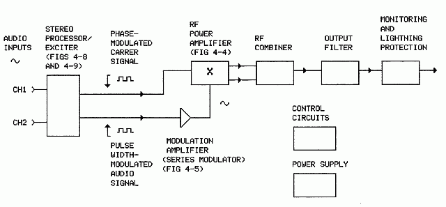 Note that the outputs of the processor/exciter consist of 1) a phase-modulated carrier at the transmitter's RF operating frequency and 2) a pulse width-modulated (PWM) AUDIO carrier, usually at around 100 kHz. The PWM stream is filtered in the modulator to remove the 100 kHz carrier and the two signals (RF carrier and now analog audio signal) are combined (multiplied) in the RF power amplifier to produce the composite stereo output signal. The composite signal is processed at the receiver to extract the original stereo audio signals. I don't think AM stereo is used much anymore, at least in the US. Hope this is helpful.. Max [1005] [Sun Jun 29 11:54:12 2008] viewcoms. max in our country radio transmitter is ilegal i heard that is in india . sir any idea to make transmitter in legal purpose houw can i get licance or any friquncy that is free for transmitting or hobby purpose any ligal sdvice if you know then give idea to solve my problame thanku sir [306] [Sun Jun 29 15:46:46 2008] max...... Illiraj55, I don't know how to get a broadcasting license in India but, like many places, if you have the equipment, there is not much that prevents you from broadcasting WITHOUT a license. (I didn't actually say that..) My suggestion is to use FM. FM transmitters are generally simpler and cheaper, antennas much smaller, and coverage (transmitting range) is usually equal to or greater than AM for wattages less than 100 or so. I don't know if low-powered FM transmitters are available in India, but they are available worldwide. Type into Google terms like 'low-power FM', 'LPFM', 'pirate radio', 'FM transmitter', etc. Hang around pirate radio forums like alt.radio.pirate or alt.pirate.radio: groups.google.com/group/alt.radio.pirate/topics?hl=en&lnk=srg groups.google.com/group/alt.pirate.radio/topics?hl=en&lnk=srg Drop a question on there about where to get transmitting equipment. Some sources that I know about are: www.ramseyelectronics.com kits mostly; require soldering www.northcountryradio.com kits; require soldering, adjustment skills, test equip www.progressive-concepts.com ready-built mostly There are many others. Importation is a problem in some countries. I don't know about India. It appears that the FM band in India extends from about 90 MHz to 108 MHz, about the same as everywhere else in the world. For a list of FM stations in India, see: www.asiawaves.net/india-fm-radio.htm Avoid frequencies on the list. Max [1739] [Mon Jun 30 12:49:44 2008] viewcoms. thanku max for your coparate i will quick come a anew topic thinku illiraj55 [87] [Sun Aug 17 10:48:19 2008] classe... -Can the unit run without load? -We know what bifilar means but it is not seen in the pictures. [114] [Mon Aug 18 06:00:33 2008] viewcoms. Yes, the transmitter can be operated without load. The output signal will be distorted. Why would you want to operate it without load? Bifilar? The white and black conductors shown in the photo make up the transformer primary winding. Note that the conductors are parallel with one another and that each occupies the whole circumference of the torroid core. (The secondary, under the electrical tape, is not bifilar wound.) Max [429] [Mon Aug 18 10:49:43 2008] amblog... notify graphical representation [41] [Sat Aug 23 05:07:09 2008] viewcoms. Without load incase of bad loadtuning or something. To know that the tx will survive. :-o [101] [Sat Aug 23 07:39:35 2008] viewcoms. If minimal drive current (<200 mA) has been acheived and class-e operation has been verified with an oscilloscope during initial tune-up, mis-tuning the output filter will not cause excessive currents or high voltages on the drains of the output MOSFETs. Arcing in the output filter capacitor or antenna tuning capacitor could be more troublesome. Be sure to use transmitting-type (high-voltage) capacitors in the output filter and antenna tuner to minimize the likelihood of arcing. Follow the guidelines given in the power supply section of the article to minimize the possibility of blowing the output transistors should arcing occur. Max [659] [Fri Aug 29 16:04:35 2008] amblog... Hay! (in LV) Ja Jums gadījumā ir zināmi mērījumi par raidītāja izejo�o jaudu, kā piem. Output 200 watt apraides zona km (brīvā un masīvā vidē). [321] [Sun Aug 31 05:47:10 2008] viewcoms. Hello Latvia! I think this is asking the transmitting range, or how much coverage area, the 200-watt transmitter provides. The answer is 'it depends'. On a clear channel at night the range could be hundreds of kilometers. On a typical well occupied channel on the upper end of the medium-wave broadcast band in the daytime the range might be 50 km. At night maybe 25 km. Maybe more, maybe less. A guy reported listening for the station one night in mid-winter at a range of about 2000 km. Nope, didn't hear it. Max [567] [Tue Sep 2 14:31:22 2008] viewcoms. Hi Max, Great transmitter design (Class E 200w.) I'd like to convert some of my LPB and Radio Systems transmitters or build new ones. I use them for carrier current operations in seniors retirement buildings. I head a not for profit group that provides senior citizens with radio listening they actually can enjoy! Commercial broadcasters and advertisers no longer care about the baby boom generation. worldsupercaster@yahoo.com [468] [Sat Dec 13 04:21:08 2008] classe... This is just the info I have been looking for. Back to the bench and the junk box for now. 73's KQ2P [113] [Sat Dec 13 07:12:03 2008] viewcoms. Glad you found the info useful, KQ2P. Max [88] [Tue Jan 12 09:07:06 2010] viewcoms. I am contemplating on building a class E transmit/receiving station at home and am curious if you could tell me what your daytime range was with 200W? I plan to operate base to mobile on the bottom of the 160 meter band. Everyone usue 2 meters and I want to do it like they did before WW2. I know nightime range should be great, but what about groundwave in the daytime? [394] [Wed Jan 13 06:44:56 2010] viewcoms. Hi kc5dsw74ci, Yeah, that's the way they did it in pre-VHF FM days (I read). The daytime range of the 200W transmitter with the antenna shown in the article is comparable to a small local AM broadcast station. With a car radio it's about 10 miles noise-free; maybe 25 miles if you're willing to put up with some noise; maybe 50 miles with a communications receiver/antenna or with a good portable AM radio (like the GE Superadio) at a quiet fixed location. Max [487] [Fri Feb 19 05:05:46 2010] viewcoms. You did an ultra fine job dr om Max. Very clear schematics, photos, infos and very simplified technical and procedural explanations abt all aspects. Hope some day to upload and a PWM modulator suitable for this rig to make us completely happy. Thank for sharing your hard work with us. Fotios/SV1CDX/Athens Greece [378] [Fri Feb 19 06:06:02 2010] viewcoms. Thanks Fotios. Max [39] [Fri Jan 28 11:33:38 2011] viewcoms. Love the site Max, I've been back many times over the years. I have a question concerning frequency scaling of the transmitter. Would these devices work at say 7 MHz or higher? I'm wondering about the practicality of using this on the amateur bands, or nearby them ;) [294] [Sun Jan 30 15:20:03 2011] viewcoms. The IRFP350LC and similar devices probably will not work well at 7 MHz or higher at anywhere near the power levels of the 1710 kHz transmitter. The gate capacitances are too high. A lower powered device, like the IRF737LC, would be more likely to work in that range. You might checkout http://classe.monkeypuppet.com/ and/or http://www.classeradio.com/ . There appears to be some pretty good info on MOSFET-based class-e transmitters for the ham bands on those sites. Max [410] [Mon Jan 31 06:33:50 2011] viewcoms. I am familiar with the class e radio site. Thanks for the reply, and best of luck with your projects. [114] [Mon Feb 21 18:30:22 2011] viewcoms. HI MAX I wonder ,can we use a " bigger" transistor than The 2 N2222 type,like the Bd 139....as the driver,or a more high power transistor than the 2N2222,or how to boost the 2N2222 power. Thanks Darren [257] [Tue Feb 22 06:01:21 2011] viewcoms. Darren, Yeah, it would appear that efforts to get ever more power from class-e MOSFET amplifiers at ever higher frequencies means driving the gates ever harder. Yep, drive those gates harder! Thanks for the comment. Max [281] [Tue Feb 22 07:25:37 2011] viewcoms. Thanks Max I lived in a country that's hard to find a specific Mosfet ,So there's only Fets here with has a high input capacitance ,meaning it needs a higher "power" driver,since I can't "find" a IXDD 414 Ic here, browsing the Internet I found Your Article ,a very good article, Reading it Something cross my mind ,can We modified it by making the driver transistor with a higher power one like a darlington Transistor,or Like I wrote before a BD 139,modified /used a "full" 4049 IC to drive each transistors? Darren [593] [Tue May 17 04:27:15 2011] viewcoms. I like to use a DDS but don't want to divide the signal by 2.....is there an other way than using the cd4013?? Thanks Henk from New-Amsterdam, The Netherlands [192] [Tue May 17 06:45:10 2011] viewcoms. Henk, Something like this should work: 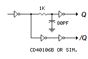 Max [75] [Sun May 29 11:10:53 2011] viewcoms. hi [12] [Sun May 29 11:11:53 2011] viewcoms. hi. I designed a 500watts class F transmitter. do you want that i send to you my map? [102] [Mon May 30 06:02:25 2011] viewcoms. Hi hi, Sure, send it. Max [50] [Sun Jun 12 21:10:16 2011] viewcoms. Hi Max; Can you please give me more details about antenna design? (the length of the radiating element, aproximate real and complex impedance,etc). Best regards from Venenezuela [222] [Mon Jun 13 10:51:41 2011] viewcoms. Hi Venezuela, I'm no antenna guru, but here's how I understand it: The most important dimension for a radiating element is its length relative to the length of the radiated wave (wavelength)*. For maximum transfer of energy from the radiating element to the radiated wave (the best match) the length of the radiating element should equal some multiple of half the wavelength. (A quarter-wave antenna is electrically a half-wave antenna as seen by the excitation source; the grounding system - the counterpoise - makes up the "missing" portion.) In a real antenna, the match will occur when the radiating element is slightly shorter than half the wavelength - the diameter of the radiating element also comes into play; the greater the diameter, the shorter the radiator. If the length of the radiating element is ideal, the impedance at the feedpoint (the midpoint of a half-wave radiator or the end of a quarter-wave radiator) will be non-reactive, it will look like a resistor to the excitation source (transmitter) - that is, current will be in phase with voltage. As the length of the radiating element or the excitation frequency is varied from ideal, the impedance at the feedpoint will begin to depart from real - it will look more and more reactive (or complex, consisting of a real and an imaginary component). That is to say, voltage and current become ever more out of phase. In the case of the radiating element being shorter than ideal, or the frequency being lower than ideal, current will lead voltage. In the opposite case, the radiating element being too long or the excitation frequency being too high, voltage will lead current. The antenna tuner components, usually located at the base of the antenna, compensate for these affects so as to make the antenna appear non-reactive to the excitation source. The inductive component delays current, the capacitive component delays voltage. Combining the two allows adjustment to a specific impedance. In the case of the antenna shown above, the inductor could be thought of as over-compensating for current lead, and the capacitor as over-compensating for current lag. By adjusting the values of these two components, the antenna can be made to look like any impedance to the exciter or, conversely, any antenna can be made to look like a specific impedance (say 50 ohms). The thing to remember about antenna tuners is that they can only partially make up for radiator inefficiencies. If the antenna is grossly short relative to it's operating frequency, no amount of compensation will make up for ground losses and/or losses in the tuner components. As for what specific capacitor/inductor combination will match a specific antenna to a specific impedance, I think it's best to take an experimental approach. Make the components adjustable and tune for best match. (See the antenna addendum above.) If you really want to calculate actual values (and can spare $45), refer to the ARRL Antenna Book. (There are sites which claim to offer the book free as a download, but my anti-virus software warns me not to visit those sites. Visit at your own risk!) *Calculate Wavelength λ = c/f where λ is wavelength in meters, c is speed of light in meters/second (300,000,000) and f is frequency in Hz. Or there's λ/2 = 468/f, where λ/2 is half-wavelength in feet and f is frequency in MHz. Hope this is helpful, Max [13] [Wed Jun 15 20:07:38 2011] viewcoms. Thanks Max, I forgot put my name: Anthony! Let me ask you something, what do you think about use a EE ferrite transformer (switching supplies,etc) in the transmitter? In this side of the world it's extremely hard to buy on internet or find out RF parts like toroids or high speed mosfet. For output capacitor, I'm making it using aluminium and screw&nuts, hopefully it will can handly safety at least 5000V considering futures "changes" in the trasmitter power. In the other hand, how do you protects the transmitter for lightning and static? Thanks again for you time and the good explanation of the antenna system. [704] [Fri Jun 17 06:21:53 2011] viewcoms. Hi Anthony, Whether or not a ferrite transformer core would work in the circuit depends on the frequency you want to operate at. The ferrite core's inductance coefficient, its AL value (uH/100 turns), may be too high. You can check this out experimentally by first running the numbers through Mallory's equations or using the calculator to find the value of the resonating capacitor/s. Wind a few turns on your core, parallel with a capacitor of the calculated value and check the resonant frequency with a signal generator and oscilloscope. Add or remove turns as necessary until you obtain resonance at about 1.29x your desired operating frequency. If you are not able to obtain resonance with the calculated capacitor value, the core likely will not work in the application. The adjustable exciter compensates somewhat for variations in component values (L and C) but won't compensate for a large discrepancy. Other than the DC-grounded antenna (through the antenna tuner) the system has no lightning protection. So far it's had no problems with lightning. An inline lightning arrestor wouldn't be a bad idea though. Max [13] [Sun Jul 10 03:46:10 2011] viewcoms. Thanks again; What do you use to hold the mast? I can see on the pic's that you use some kind of plastic rope! I ask that because some metal would act as a reflector and will change the radiation resistence and how it radiates, correct? [281] [Sun Jul 10 05:32:36 2011] viewcoms. The mast is guyed with plastic-coated clothesline wire. (Does anyone use clothesline wire nowadays?) The guys are insulated at both ends. Since the guys are very short relative to the antenna's operating wavelength, I doubt they have much affect. If the lengths were a significant fraction of λ/2 they would need to be broken up with more insulators. Max [441] [Wed Dec 14 15:09:45 2011] home..... Hi Max I really like the Class E 200 Watt transmitter of yours. I noticed you did not include the output capacitance of the FETs. Does this cause any problems that you have found? Thanks Don [217] [Thu Dec 15 06:52:15 2011] viewcoms. Hi Don, No, I didn't have any problems related to FET output capacitance but I should have mentioned it in the article. It could be significant when the tank values calculation calls for a capacitance value below maybe an order of magnitude above the MOSFETs' output capacitance. This could be the case when calculated tank impedance comes in "on the high side" - over 50-100 ohms or so, ie., when high power, high supply voltage and/or high frequency is called for. The FET output capacitance should be subtracted from the calculated value. The adjustable exciter provides for duty-cycle adjustment during tune-up. This compensates somewhat for variations in component values. As mentioned in the article, the specified FETs probably won't work well in the circuit above 2-3 MHz. Thanks for the comment. Max [810] [Thu Mar 1 08:24:29 2012] viewcoms. Hi Max, I have been using your design for some time now. Mine is crystal driven at twice the frequeny. I would like to use a PLL or VFO. The only thing is that both have a sinus wave signal. Is there a solution how to convert the sinus into a square wave? Thanks Henk, PA3EMX [319] [Fri Mar 2 05:48:49 2012] viewcoms. Hi Henk, The circuit in Figure 2 of the article should work with a sinewave input if the amplitude is greater than 4 volts (p-p) or so. Almost any amplifier, if driven hard enough, will act as a sinewave-to-squarewave "converter". The circuit below should work OK with a sinewave input amplitude considerably below 1 volt. 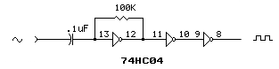 Glad you've found the circuit useful. Max [347] [Sat Mar 3 16:20:56 2012] classe... Hi Max, Thanks for the swift update. This was only 5 minutes work to get it all inaction with my home made PLL. It is getting better all the time!!!!! Thanks and have a nice weekend6+- Regards, Hank [251] [Wed Apr 25 15:35:10 2012] classe... Hi Max. Could you tell me how to calculate C1 and capacitor in parallel to other working frequencies ... Many thx, William [144] [Thu Apr 26 07:08:24 2012] classe... William, I don't know how to calculate the value of those capacitors. The values shown were derived experimentally during the tune-up process (step 3). The 1250 pF capacitor was added across C1 to acheive minimum driver current within the adjustment range of C1. A combined value about 1/3 the value of the resonating capacitors (5500 pF) might be a good rule of thumb, but that relationship might not hold if the operating frequency, power and power supply voltage are radically different from those of the described transmitter. Likewise, a different transformer core and/or final transistors might result in a different relationship. Sorry I don't have a better answer to your question, but thanks for asking it. Feedback gives me a chance to re-think these things. I may modify the original article to clarify the tune-up procedure regarding C1. Max [1155] [Thu Apr 26 09:35:20 2012] classe... Thanks for quick response. I want to use your design for 7MHz with other mosfet. I'll have to do some tests to see the results. Max thank you very much, congratulations on the article William [225] [Tue Aug 21 22:09:25 2012] classe... Hello! I just wanted to ask if you ever have any problems with hackers? My last blog (wordpress) was hacked and I ended up losing months of hard work due to no data backup. Do you have any methods to protect against hackers? [282] [Wed Aug 22 06:41:51 2012] classe... Weird junk - some of it innocuous, some potentially destructive, most merely annoying - comes in every day. I examine the access log and deal with issues as they come up. Revealing exact methods might be revealing too much. BTW, your post comes close to qualifying as "weird junk". Max [419] [Sun Sep 29 06:10:01 2013] classe... A tip of the hat your way from Texas. A real nice design and a project that looks like even I could build it. Nice work... I'd love to hear your station but I've got a station at 1700 here in the Dallas Texas area that eats up the band... At least it is "comedy" and not, yet another "Blather Radio Outlet", or freaking Sports Radio. I sure miss music on AM at night since KOMA changed format and call letters to KOKC and more "Blather Radio". The ONLY AM music choice now days (or in this case nights) is WSM Nashville with 5kc bandwidth IBOC compatible AM. I get better bandwidth and sound from a telephone..Oh well.. [686] [Sun Sep 29 06:12:45 2013] classe... Nice comment. For sure music is dead on AM, and I wonder sometimes if AM itself will be around much longer. WSM is covered here by KGAB in Cheyenne. I get CBC-1 out of Winnepeg and/or Calgary. Makes reaching up and turning on the radio in the middle of the night still worth the effort.. Max [371] [Tue Oct 8 05:23:54 2013] classe... [Darren, Sorry, the server software thought your post was SPAM. Here it is:] HY Can I used several module/transmitter and combine to Make a higher power Output transmitter Darren [141] [Tue Oct 8 05:36:04 2013] classe... Probably. That big T-400-02 core could be wound with multiple primaries driven in-phase, with a single secondary driving the output filter. Could be tricky though. Max [204] [Fri Apr 25 04:19:32 2014] viewcoms. Max, did you ever measure the impedance at the base of the antenna? I'm looking for ohms and reactance, if you know off hand. Thanks [162] [Fri Apr 25 05:12:36 2014] viewcoms. I've never measured it directly with a bridge but it roughly calculates to around 800 ohms - highly reactive (capacitive). Max [112] [Fri Apr 25 13:42:30 2014] viewcoms. Interesting. Similar designs state around 3 ohms real, and around -550 ohms reactance (capacitive). I would like to try an autoformer type match for simplicity. It will be lossy, but the components would be cheaper and smaller, if you went the toroid route. [280] [Sat Apr 26 07:58:34 2014] viewcoms. With ground resistance an order of magnitude or two greater, that 3 ohms real means the 200-watt transmitter radiates a watt or two.. Makes a good case for confining unlicensed broadcasting efforts to 3 meters (FM). :) Max [235] [Thu Feb 5 06:06:05 2015] classe... Hi Max please give us all formula of your calculators in this page. Best Regards J.RahmaniPour [125] [Tue Feb 10 08:15:32 2015] classe... J.RahmaniPour, Done! Formulas are now shown on all of the calculator pages. Thanks for the suggestion. See also Mark Mallory's article. Max [109] [Sat Mar 28 05:22:11 2015] classe... [repost from maxmcarter.com comments] Some time ago I'm working with an AM transmitter that works on 7 Mhz. The development of my team is based on his work, I used the IRFP350 mosfet which I managed to do work without problem on that frequency. The redimiento transmitter (power amplifier) has been for over 90% efficiency. The modulator used is a PWM and ultimately the power obtained in the range of 40 meters is 225 watt 28 volt power .......... as seen publication, which I appreciate very much, has served me to develop my project. [522] [Sat Mar 28 05:29:23 2015] classe... Hey, I'm glad it works! I didn't suppose there would be much interest in AM on 40 meters. Thanks for the post. Max [122] [Wed Oct 14 18:34:52 2015] classe... Hi Max, Very nice info. I try to build Class E AM Transmitter based on this project with a minor change in working Frequency and power level (1404 Khz and 300W carrier). For power mosfet, i use two of 45N60. but til tday, my trasnmitter isn't work well. Would you like to review my project schematic? Please send your email address to risam1984@gamail.com and i'll send my schematic, DDS firmware, waveform capture and some picture of tramiitter. Thankyou. Risam, YD1FNM [559] [Thu Oct 15 05:30:41 2015] classe... Hi Risam, Sure, send the items to me at this address:  Send along some details of your efforts. I'll try to be helpful. Max [118] [Tue Nov 3 07:06:58 2015] classe... After some component changes and circuit rearrangement (parallel 20N60C3s in the final), Risam (in Indonesia) got his transmitter built and working (350W, 1404 kHz). It burned out his dummy load, a "good" problem. :] He sent some photos. Max [149] [Sat Dec 5 06:15:54 2015] classe... Hi Max i am building transmitter with 4 fs14sm18a balanced 2x2 an it works ill get 250 watts @ 52 volt with 5,5 amp. i have also build an pdm 2x irfp260n the problem is i can't get the filter right, trying Butterworth tee filter 4 pole Fc 12,5Khz 8 harmocic 100Khz @ pdm freq. 9.5 ohm impedance but stil much noise on the dc how can i calcutate an pdm filter? regars marcel [414] [Sat Dec 5 09:48:26 2015] classe... Hi marcel, I calculated for 12.5 kHz using ARRL's chart for a 4-pole Butterworth and got these numbers: L1 92.6e-6 C1 2.48e-6 L2 224e-6 C2 1.03e-6 The filter looks good in LTspice with "0-ohms" source resistance: 100 kHz -80dB with virtually no loss in the audio range. It's a little peaky around 12.5 kHz, but that's no big deal. With that source resistance set to zero, it's not really a Butterworth, but who cares.. :) Likely your modulator has neither 0 ohms nor 9.5 ohms source resistance. Hope this is helpful. Regards, Max 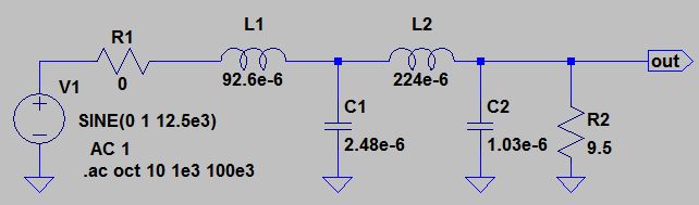 "0 ohms" source 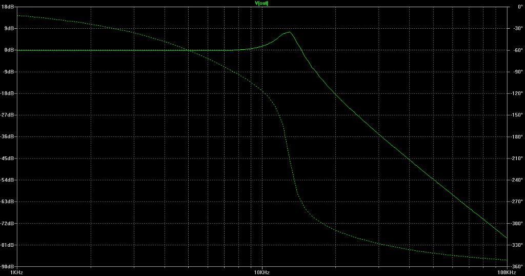 9.5 ohms source (true Butterworth response) 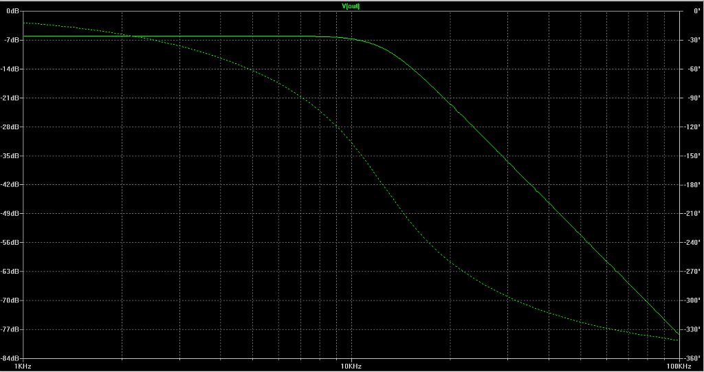 [403] [Sat Dec 5 13:31:09 2015] classe... Thanks for your fast response, i tried it 93uH, 2.5uF-225uH, 1uF on t300-52 cores 1.5 mm2 isolated wire but i still have "fish" tails on the dc line.... and 100Khz carriers.... before the filter the square wave is almost perfect left the side when the square wave goes high i see a spike under the floating ground down??? pwm stage - 6n137 opto - tc4452 fet driver 2 irfp260n quit firm the pdm system is very nice but the filter driving me crazy.... i am also working on tube pdm but with more succes... [555] [Sat Dec 5 17:31:04 2015] classe... marcel, My guess (only a guess) is you're getting some induced pickup on your scope probe ground lead(s). Good luck! Max [168] [Sat Dec 5 17:51:44 2015] classe... For what it's worth, MCM Electronics has a 400-watt Class D audio amp that looks like it would make a great AM modulator. Couple that into the DC line through a large electrolytic capacitor. (The power supply must have a high-current inductor on the output, ahead of the capacitor. See Fig 3, option 4 above.) Max [344] [Wed Dec 23 10:21:55 2015] classe... it works, much reading.... and bought capacitors -940- series made the filter as calculated nice. one core (94uH) on a T300-52 reaches 40 degree Celsius maybe ill go to 125Khz pwm to get less heat (7 degree less) and more filtering 10 th order... i am looking for a differential probe to solve measuring problems thx for youre help [376] [Thu Dec 24 08:35:15 2015] classe... marcel, Likely most of the heat is being generated in the core material. You might try a lower permeability material (2 for example) with more wire turns. Max [184] [Sat Dec 26 05:41:36 2015] classe... max, yes, but then again it makes the filter huge T400-2 for 93 uH I am using isolated wire 1,5 mm 2,6 with isolation maybe single layer air coil on pvc tube ? even bigger I noticed thus: 93uH on T400-2 224uH on T400-52 something to experiment with again [330] [Sat Dec 26 13:47:30 2015] classe... and what about stacking 2 toroids? for the first pole.... [75] [Sun Dec 27 08:57:58 2015] classe... Yes, stacking 2 cores should result in a cooler inductor. 40°C actually is not bad, especially if the circuit is carrying 200-300 watts (or more). 100% efficiency is not achievable. The single-layer air coil would be another interesting experiment. Have fun! Max [307] [Thu Jan 7 09:45:52 2016] classe... A very useful and informative articles for electronics student, professional, and hobbyist like me. Congratulation Max..its a great job! Nest srrs325@gmail.com [177] [Fri Jan 8 05:18:05 2016] classe... Thanks for the nice comment, Nest. Max [61] [Sun Jan 24 14:55:03 2016] classe... and what about edt49-n87 transformer as filter would that work out. it is used for 1Kw smps at 100Khz have someone tried that already? [156] [Mon Jan 25 05:36:19 2016] classe... My guess is that it would not. The permeability of the core is likely too high. The box above labeled "Unknown AL Value" suggests a way to check it out. Max [183] [Thu Jan 28 10:55:02 2016] classe... Max, how do you compute your antenna top hat? Ness srrs325@gmail.com [106] [Fri Jan 29 05:37:46 2016] classe... Ness, There was little computing. The antenna was simply made "as tall and fat as possible". At 1.71 MHz, a quarter wavelength is 44m [300/1.71/4]. At 17m the antenna was obviously short, so the top hat was added. The top hat consisted of elements from an old TV antenna and has since been partially destroyed by an ice storm with little difference in the tuning. You might check out the activities of the "LowFERs", folks who operate in the 160-190 kHz license-free (in the US) longwave band. Transmitting antennas in the longwave part of the spectrum often employ enormous top hats and loading coils. See Transmitting Antennas and Ground Systems for 1750 Meters for some longwave antenna wisdom and links to more longwave stuff. Max [13] [Wed Feb 17 15:56:46 2016] classe... hi max: to get back on the pdm filter, using edt49 for pdm filter I have found something by : nautel naa25b a 450W carrier module with pdm and filter using small ferrite transformers they will stack 4 of them to get 1Kw carrier nice system, maybe some inspiration btw: thanks for you're ideas and support regards, marcel [389] [Fri Feb 19 05:26:11 2016] classe... Glad you got the modulator working to your satisfaction, Marcel. Thanks for the nice comment! Max [134] [Thu May 26 14:24:27 2016] classe... Amazing comprehensive description !!! A tip of a hat from Greece. I am just collecting components to build your project. Congrats. iokaral@yahoo.com [167] [Fri May 27 07:39:02 2016] classe... Thanks iokaral, Glad you found the information useful. Good luck in your efforts. Regards, Max [142] [Wed Jun 1 01:54:43 2016] classe... Hi Max Voltage of those MICA .0055 uF caps please? Thanks [79] [Wed Jun 1 07:08:05 2016] classe... 600 volts should be OK for power supply voltages ≤100. Max [37] [Thu Jun 2 06:40:00 2016] classe... Keep up the good job!!! Just in hand IRFP360LC and IRFP350PBF. Which one to use up to 1.5MHz instead of IRFP350LC? John [159] [Fri Jun 3 05:27:24 2016] classe... The IRFP350PBF has lower gate capacitance. I'd probably go with that one at 200 watts. Max [114] [Thu Oct 20 12:50:22 2016] classe... hi,can you send me the schematic of antenna tuning for 1710Khz ? Thanks Roberto Milan Italy marinelluccia1 --- a t--tiscali.it c [186] [Fri Oct 21 09:36:06 2016] classe... Roberto, The circuit shown in Figure 7 of the transmitter article above should work for most vertical antennas shorter than 1/4 wavelength with a ground plane. Follow the procedure under "Tuner Adjustment". Without knowing the impedance of your antenna it's not possible to specify exact component values for the tuning circuit. This antenna impedance article, written for a shortwave spark transmitter, provides some information on characterizing an antenna. And here's a calculator you might use once you know your antenna's impedance: Impedance Matching Network Designer. Hope this is helpful. Max [13] [Fri Oct 28 12:27:03 2016] classe... Hi Max. Talking about the compression mica trim cap 750pF. Is this 750pF the average value? The maximum? Minimum? Thanks a lot [147] [Sat Oct 29 06:10:23 2016] classe... The value specified for the trimmer (C1) is the maximum value of the unit I used in the circuit. The trimmer is adjusted for minimum drive current during the tuneup procedure. The value for this and the 1250 pF cap. adjacent to it were arrived at experimentally. I don't know how to calculate the actual value. It depends on the operating frequency, the drain-source capacitance of the output transistors and other factors. The value shown for C1 should be good for a range of factors, but expect to do some experimenting here. BTW, the number 2 in parentheses (2) next to the 1250 pF cap. refers to note #2. Max [647] [Sat Nov 19 08:31:33 2016] classe... Hi my friend and congrats on your amazing work. I've got an Arduino-Si5351 digital combination which gives 3Vp-pclear square wave. Any clue how to achieve more than 4Vp-p needed for the exciter? I've been using a scmitt trigger (CD4069 - Vdd=5V) and everything seems good. Calculated for about 1.5 MHz - 45V PS and everything seems to be good so far.My handmade 50 Ohm Dummy load gets really hot while the output transformer and IRFP350LC's remain just worm. Supplying only 22V at the moment the only problem is that pulls 4.5A (no good I think). Any clue please? Many thanks and keep up ! John- [639] [Sun Nov 20 08:52:32 2016] classe... Thanks John, If the 3Vp-p source works OK, I don't think there's any harm in continuing to use it. Apparently your CD4069 Schmitt trigger is doing a fine job of amplifying the 3-volt signal to a 5-volt signal. On the possibly excessive final current (4.5A @ 22V), first recheck the tuneup procedure. Verify the driver current dip and the oscilloscope waveforms on the drains and at TP1. Verify with the scope at TP1 (or use an in-line power meter) that you're getting something like 90-95 watts output (190-195Vp-p @ 50 ohms). If output power is below the 90-95 watt range, again check that the final is tuned up according to the procedure (driver current minimized and good waveforms). If necessary, increase the number of turns on the output transformer secondary to bring the power up (to 45-50 watts). DC draw should be about 2 amps @ 22V. Redo the tuneup procedure. If the output power is within or near the 90-95 range, then you're looking at a 350-375W transmitter at 45 volts. At 100% modulation output power peaks at 1400-1500 watts which is excessive for the finals. Lower the number of turns in the output transformer secondary to bring the power down to ~ 45-50 watts at 22V. Redo the tuneup procedure. The numbers are ballpark. Basically, you're trying for better than 90% DC to RF efficiency. Hope this is helpful, Max [1510] [Sun Nov 27 00:51:56 2016] classe... Hi Max. I've read a lot about Transient Protection (ESD)of MOSFETS. I'd like to know your point of view and if TVS diodes is suggested which value please for Drain-Source and Gate-Source Protection is suitable?). Something else:Voltage measured on both Gates is about 4.46V. Is that correct? Thank you very much Petro [360] [Sun Nov 27 09:20:26 2016] classe... Petro, I've tried applying TVS (Transient Voltage Suppression) diodes to an active receive antenna which was suffering failures due to lightning transients. Their effectiveness in that case was approximately zero (not effective at all). I've no experience using them for protecting MOSFETs. My guess is they would be no more effective than the protections built into the MOSFET devices themselves and might contribute to increasing the capacitance seen by the drivers. The biggest cause for failure of the MOSFETs in my experience has been when the DC fuse in the power supply let go. This is the reason I don't recommend fusing the DC line from the power supply. The fuse should be located on the primary side of the power supply transformer (see "Power Supply" above). If you're experiencing failures due to transients, there's probably no harm in trying TVSs. On the gates they probably should rated around 15 volts or so, on the drains maybe 300 volts. The voltage on the gates is best observed with an oscilloscope using a 10x probe. You should see a square wave (more or less) switching between about +0.5 volts and +9.5 volts. The voltage read with a DC meter will be somewhere near the middle of those extremes (~ 5 volts DC) depending on the settings of the exciter. Max [1199] [Tue Dec 20 06:28:02 2016] classe... Please help. Everything works fine apart from the directional watt meter which is completely dead. I've been trying and trying but not the slightest movement.. Installed 1mA analog meter, T50-2 Iron Powder Toroidal Core, coil with 28 turns of wire, shielding grounded at one end and AD835AN Voltage Output 4-Quadrant Multiplier IC. (Nowhere to be found this AD835N but only AD835AN on Ebay. The 1mA meter has been checked and it's OK. As far more experienced than myself any clue about the culprit please? Am I to suspect a defective IC? Thanks a lot Max [581] [Thu Dec 22 09:15:51 2016] classe... With the circuit "completely dead, not the slightest movement" it has to be a wiring error, missing component, wrong value component or dead IC. You might try verifying 5 volts on the cathode of the zener diode. Could the zener be installed backward? Max [289] [Mon Jan 16 21:22:36 2017] classe... Hi Max About the power meter; two power scales are required. I�ve already scaled the power meter (1mA) to show the correct Watt readings ( 0 to 300 Watts ?ANALOG scale). The question is how to make a new readout scale for the SWR. Of-course ANALOG but the full scale rating? Low level must be (1). High level (???). Can you please help? Many thanks George [432] [Tue Jan 17 07:43:05 2017] classe... George, The circuit in Figure 6 is a "squaring" circuit and produces a linear power reading (directly in watts) in both the forward and reverse direction - the scale is the same. The circuit is not suitable for reading VSWR (Voltage SWR). The scale on a VSWR meter is expanded on the left and compressed on the right. The scale using this circuit would be compressed on the left, making reading difficult. Or maybe I'm missing something in your question - always a possibility. VSWR can be calculated from reflected power as follows, VSWR = (1 + √PRFL/PFWD ) / (1 - √PRFL/PFWD ) where PRFL is reflected power in watts, and PFWD is forward power in watts. Or use this calculator. Max [549] [Fri Jan 20 15:54:17 2017] classe... Hi again Max Maybe I am missing something in your reply. You say: "The circuit produces a LINEAR power reading in both the forward and reverse direction". You also say: "The scale using this circuit would be COMPRESSED on the left.." But compressed scale is a non linear one. Am I right? Please correct me. Many thanks. George [361] [Sat Jan 21 07:31:57 2017] classe... Hi Max. Don't bother answering as I got what you mean. Linear reading refers to power scale while compressed scale refers to VSWR. Thanks a lot. George [168] [Sat Jan 21 11:03:57 2017] classe... George, I misspoke a little in that reply. There's nothing sez you couldn't superimpose a VSWR scale on your wattmeter. If you'd like to do that, and have the artistic talent or computer graphics skills to draw it, use the calculator to locate the graduations. You will need to bring out to the front panel a separate SCALE adjust pot and a POWER/VSWR selector switch. Set the meter to full scale with the transmitter powered and the FWD/REFL switch in the FWD position - this will correspond to infinite (∞) VSWR. Read VSWR in the REFL position. Another option would be to have two meters, one for power (FWD) and one for VSWR (REFL). These are often seen in stand-alone power/VSWR meters and commercial transmitters. BTW, the wattmeter circuit will work with virtually any DC meter by changing the value of the scaling resistor/s. Your choice on meters. Regards, Max [168] [Thu Feb 9 01:26:18 2017] classe... Hi Max. Finally got it to work thanks to you! Here we are: I stuck two cores together T200-2(on hand)and hit 231 watts (CW). Power supply 50Vdc, efficiency 92.5%. At 25 volts, efficiency = 96%!. Wave forms are perfect - nothing gets warm but the dummy load is boiling. Question: could the finals withstand this power during 100% modulation or I have to lower the supply voltage a bit? Once again thank you for the fantastic article. George [492] [Thu Feb 9 07:59:43 2017] classe... Thanks for the nice remarks, George. 231 watts CW would translate to 924 watts peak at 100% modulation, or about 1000 watts peak input power at 92.5% efficiency. It would be pushing things a little but it would probably be OK. But then again, the difference between 231w and 200w is only about 0.6 dB. You might prefer having the safety margin that lowering the power supply voltage a little would provide. As mentioned in the original article, make sure there's no fuse in the DC line from the power supply to blow. Keep the finals well-cooled. Good luck! Max [663] [Sat Apr 15 07:30:50 2017] classe... Hi Max Hope all is well with you. After a break I resume work on the project and am about to finish all. Still unmodulated, 50V Supply, 304 Vp-p, >93% efficiency. Just a few questions please. 1) Thinking of using something like that as a modulator amplifier [link] which of course is a non isolated transformerless amplifier to be directly connected to a 4-8 Ohm Speaker. According to your description I need an external isolation transformer (Figure 3, Option #3). Talking about a common isolation transformer you mean: 1:1 as we use in Europe 230 VAC / 230 VAC 500 WATTS? Or a special made one (optimized) for best sound quality? 2) Regarding the Peak Limiter Overload Indicator, you say: (The circuit(s) are placed between the (+) modulator output (Figure 1 connection), or the power supply output (Figure 5 connection), and the center tap of the transmitter output transformer.) I don't get this "between". The schematic shows the cathode of 1N3890 going to the (+) modulator output which anyways goes to the RF Output Transformer (Center Tap). Is that OK or I misunderstand something? 3) When the Modulator is not attached (Modulation Off), I use a shorting jumper across the Mod.input terminals. In that case the cathode of 1N3890 keeps connected to the CT. Is there any problem with that? 4) (Alternative). Let's say that we use the Option #1 - Figure 3 (your case). This public address amplifier came together with a bulky OUTPUT TRANSFORMER. Did you use this output transformer to modulate the carrier? or you replaced it using a modulation transformer instead? Many thanks Yannis [1929] [Sat Apr 15 07:59:53 2017] classe... Hi Yannis, All is well here. 1) > Thinking of using something like that as a modulator amplifier One of those amps would probably work. I don't see any specified power supply voltages; power supply voltage would need to be in the 48-50 volt range for it to work as a modulator for your transmitter. You would want to check it out with a scope under load (See: "How to Check Modulation Amplifier Power") to verify it will put out ~100 volts peak-to-peak. You might also consider this one: [link] More expensive, unfortunately. :( Before deciding on what configuration to use, read the second paragraph under "Modulation" and verify the amp is isolated (or not). Also, it must have very low terminal-to-terminal DC resistance for options 1 or 2. Remember to have your audio source connected (not powered) when you make the checks. The source cable could defeat the isolation through its shield. > > According to your description I need an external isolation transformer > > (Figure 3, Option #3). Yes, if the amp is not isolated it would need to be connected to the transmitter either with a 1:1 transformer (opt. 3) or through a capacitor (opt 4). I think a 230:230V isolation transformer would work OK. I suggest using a 1000-watt transformer at 230 VAC (for a given wattage, transformers designed for 230 volts have a lower current rating than those designed for 120 VAC). In the capacitor-coupled case (opt 4), you would need to find a 25 mH (or greater) high-current (10-20 amps) choke to put between the power supply output and the coupling capacitor per Figure 5. Finding such a choke might be harder than finding an isolation transformer. > a special made one > (optimized) for best sound quality? No, a plain old isolation transformer. 2) >> I don't get this "between". The power supply, modulator and modulation limiter are connected in series. This shows the option 1 connection: 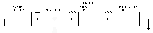 As you can see, the negative peak limiter is connected between the modulator and the transmitter final. 3) > When the Modulator is not attached (Modulation Off), I use a > > shorting jumper across the Mod.input terminals. In that case the > > cathode of 1N3890 keeps connected to the CT. Is there any problem with > > that? No problem. The diode remains reverse biased and no conduction takes place. 4) > Did you use this output transformer to modulate the > > carrier? or you replaced it using a modulation transformer instead? In this case, the amplifier's output transformer serves as the modulation transformer. It was not replaced. Max [3008] [Sat Apr 15 08:26:42 2017] classe... Thank you so much Max Please check the attached photo to see my progress on the panel and a diagram awaiting your approval. Still can not understand (due to my knowledge) the term: Terminal to terminal DC resistance. You mean the resistance of the modulation transformers secondary coil? ABOUT MODULATION: Finally this 8 Ohms you mention is that critical? If so I think could use a 4 Ohms transformerless modulation amplifier with an isolation transformer 1:2 to achieve 8 ohms. Am I right? Could you please explain to me which power supply is deemed to be a) NON ISOLATED, b) ISOLATED? I use a switching power supply ( "+", "-" and GND). Does it mean ISOLATED ? Don't worry this is the last bunch cuz I've run out of inquiries :) Take care [1173] [Sat Apr 15 08:40:18 2017] classe... Yannis, Your drawing looks good! (Better than mine.) And yes, the connection to the 1N3890 is OK. The diode is reverse biased. It conducts only when the instantaneous voltage from the power supply/modulator drops below about 2 volts. 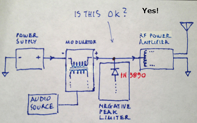 "Terminal-to-terminal " can refer to any device. In the case I mentioned, it refers the modulation amplifier. Measure from one terminal to the other.   In the case of the power supply, the measurement is from the terminals to ground: "terminal-to-ground". a) "Non-isolated" is when there is continuity (zero ohms) measured from either terminal to ground. b) "Isolated" is when there is no continuity (infinite ohms) measured from either terminal to ground. > ABOUT MODULATION: Finally this 8 Ohms you mention is that critical? If so I think could use a 4 Ohms transformerless modulation amplifier with an isolation transformer 1:2 to achieve 8 ohms. Am I right? Modern amplifiers can operate satisfactorily into almost any impedance. The real issue is the voltage the modulation amplifier can produce under whatever load is connected. The peak-to-peak voltage must be at least twice the transmitter's power supply voltage. Quoting the web article: "The test for amplifier suitability can also be stated in terms of voltage as follows: Peak-to-peak modulation (audio amplifier output) voltage under equivalent load must be equal to or greater than twice the transmitter's power supply voltage." Using a step-up transformer would be one way to derive the voltage needed to modulate the transmitter to 100%. Whether or not such a transformer would be needed depends on the voltage the amplifier is capable of producing, which depends on the modulation amplifier's power supply voltage. Max [Checkout Yannis's transmitter. It's an impressive work of art!] [1992] [Tue Aug 15 20:50:04 2017] classe... Hello Max I enjoyed reading Cat Radio story while I was here in the city, the island have no AM radio station. I want to build like what you do, but in 1611 KHz dial.. Can you help me identify on what part I need to modify aside from the antenna? Hoping for your prompt response. Elmer Isla islandradyo@gmail.com Dalupiri Island, Municipality of Calayan Province of Cagayan Philippines [461] [Wed Aug 16 10:35:00 2017] classe... Hi Elmer, The transmitter circuit(s) as shown probably would work with little modification at 1611 kHz. You might consider substituting type STP20N90K5 for the specified IRFP350LC MOSFETs in the final. I have not tried these, but the specs look pretty good. Be sure to read the posted comments of previous builders. Their experiences are educational. Expect to do some experimenting (especially if you substitute the MOSFETs). An oscilloscope is required to properly adjust the transmitter. Good luck. Max [576] [Sat Sep 30 16:48:33 2017] classe... Take a look at Yannis's dummy load. The cylinder from a 200cc motorcycle engine serves as the heatsink. Prettiest dummy load I ever saw! Max [13] [Sun Oct 1 00:15:53 2017] classe... hola max,�tengo 2 mosfet irfp 350 P serviria igual? [67] [Sun Oct 1 07:02:46 2017] classe... I think 'irfp350P' may refer to the irfp350PbF which is a lead-free version of the irfp350. The device used in the as-built transmitter is the irfp350LC, which is the low gate charge version of the irfp350. The PbF version has a much higher gate-source capacitance, higher gate-drain capacitance and slightly higher drain-source capacitance. The result is a higher output capacitance, making for an overall slower device. It may be OK at the lower end of the medium wave/longwave spectrum, say below 1 MHz and/or below 100 watts, but I couldn't say for sure. [I'm out of my depth recommending devices I have no experience with.] Expect to do some experimenting. I would be interested in the result of your efforts. Max [897] [Thu Oct 19 23:25:05 2017] classe... hola max,no consigo el irfp350lc y el integrado cd4584 (hay un moosfet irfp450lc) puede servir? ya que las caracteristicas del irfp350lc y el irfp450lc son similares en el datasheep.esp tu rta [210] [Fri Oct 20 05:58:50 2017] classe... Yes, the irfp450lc does appear to be very similar to irfp350lc, but with a higher drain/source breakdown voltage. Though I don't have any experience with the device, it looks like a good choice. On the CD4584, you might try Futurlec. If that doesn't work for you, CMOS type CD40106 would likely work OK in the circuit. Max [472] [Sat Sep 30 16:48:33 2017] classe... See Yannis Karalis's power supply here. He does amazing work! Max [13] [Thu Nov 30 07:19:07 2017] classe... Nobody has contributed here in years, but what component changes would be necessary for a shortwave at 6.5 MHz? [125] [Fri Dec 1 05:28:03 2017] classe... Faster MOSFETs would be the biggest change necessary. I'm not sure the circuit would work well even then. See the post of Sun Jan 30 15:20:03 2011; check the websites mentioned. Someone apparently has made it work at 7 MHz, see Sat Mar 28 05:22:11 2015. Max [274] [Wed Feb 14 03:57:20 2018] classe... Hello is it possible to use smaller toroids for trasformer ? [83] [Wed Feb 14 05:38:19 2018] classe... Yes. The T-400-02 shown is definitely over-rated for this application. But don't go any smaller than necessary, given your physical restrictions. Use the largest one that will fit in the space available. Stick with mix 2 (-02 powdered iron). Max [278] [Sat Feb 17 03:23:42 2018] classe... Hallo Max , the RC net into phase inverter you suggest to Mr. Henk is set for 1710 Khx only, i presume ? [131] [Sat Feb 17 05:33:21 2018] classe... No. The RC network provides a delay approximately equal to the delay through the extra inverter in the lower leg of the circuit. This is done to keep the Q and /Q outputs symmetrical. The circuit should be usable up to 5-10 MHz. You may have to adjust the values of the components to optimise symmetry. Max [264] [Thu Mar 8 08:39:03 2018] classe... LC mosfets are a bit expensive to me... PBF types could replace ? [82] [Fri Mar 9 05:44:25 2018] classe... Possibly. The PbF version has a much higher gate-source capacitance, higher gate-drain capacitance and slightly higher drain-source capacitance, making it an overall slower device. It may be OK at the lower end of the medium wave/longwave spectrum, say below 1 MHz and/or below 100 watts, but I couldn't say for sure. The 2N2222/2N2907 driver combination shown in Fig 1 is a little wimpy. If you want to try the PbFs in the circuit, I suggest substituting high-speed MOSFET drivers, such as Microchip's MCP1407, for the 2N2222/2N2907s shown. Max [714] [Sat Mar 10 03:34:26 2018] classe... And the LCPBF ? :) Vishay offer such curious type, from datasheet seems a LC model anyway... [120] [Sat Mar 10 05:10:23 2018] classe... Yeah, the "PbF" simply means it's a lead-free device. Max [82] [Sat Mar 17 03:34:53 2018] classe... Hallo Using MCP1406 thats a inverting driver should simplify the schematic at undivided frequency ? The input diode protection is good for IC driver also ? [208] [Sat Mar 17 05:54:27 2018] classe... To be clear, the alternate exciter input circuit (shown above) specifies type CD40106B (CMOS hex Schmitt trigger). Yes, the circuit eliminates the need for the CD4013 divider (depending on the frequency of your excitation source). You may have to adjust the values of the components (resistor and/or capacitor) to optimize symmetry. If you use the suggested Microchip driver chips, be sure to use the NON-INVERTING version (MCP1407). Yes, I would retain the coupling capacitor, 10k resistor and diode on the inputs to the drivers. The purpose of these components is to pull the inputs LOW if excitation is lost, shutting off both of the finals. Max [575] [Sun Mar 18 01:10:21 2018] classe... Thanks I meant use a 1407 and a 1406 complementary [65] [Sun Mar 18 14:47:06 2018] classe... I am not understanding your proposal then, but good luck with it! Max [92] [Thu Apr 12 08:07:31 2018] classe... Hello again my friend I've just tested the notorious IXDD414 Low-Side Ultrafast MOSFET Driver. The results monitored on the scope are perfect ! even in parallel arrangement (check the photo). Of course the drivers current drawn was double (about 200mA). Better efficiency and seem to be "indestructible device.." after what it has suffered by me :) I think this could be a good replacement for the "wimpy" 2222/2907 pair. Take care Max [Yannis] [See also Yannis's plywood transmitter. - Max] [357] [Sun Apr 15 23:53:07 2018] classe... How do you calculate the parallel Drain capacitors, I mean in my case the Fet's mounted by insulator to the heat sink has already 2.8 NF each, measured from drain to heat sink. (I used Mica insulators) [221] [Mon Apr 16 00:13:46 2018] classe... I use already a long time the IXDD 609CI fet driver (up to 35 Volts) with an current balun behind for Push Pull out. It runs from 1-10 mHz. Drive 2 Fet's, ( IRPF 250) each has 2NF gate capacitance. Full 200 Watts output (Broadband) by 22 Volts, 10 Amp. .. [284] [Mon Apr 16 08:23:19 2018] classe... I'm not sure a static measurement of drain-to-heatsink capacitance gives an accurate indication of output capacitance in a class-e amplifier. My understanding of it is not completely clear, but it has to do with the dynamic interaction of the gate with the drain affecting drain capacitance (the "Miller effect"). In other words, the values of the drain shunt capacitors in the as-built transmitter ultimately were derived experimentally. Mallory's equations on which the calculator is based have proven (based on the experience of other builders) to be only a rough guide. I have modified slightly the advice given in the box labeled "Unknown AL Value" to reflect this uncertainty. Also, read the box "About the Calculations". Hope this helps. Builders should expect to do some experimenting (at reduced power supply voltage!). Max [893] [Mon Apr 16 08:24:59 2018] classe... IXYS drivers seem to be the way to go, according to the comments. Max [92] [Wed Apr 18 01:09:16 2018] classe... Max, The IRFP 250 works great at 20-22 Volts with good efficiency, output is almost same as input. And by using only two 24 Volts Power Supplies in series nice sound by PWM modulation. Greetings from Holland, Hans. [235] [Wed Apr 18 006:00:41 2018] classe... [delayed post] Hello Max, I like to build a tuned Gate/Drain section because in my 60 KW Nautel Medium wave TX there are in each PA section tuned sections to, in the gate and drain. And in tuned position i see a nice and clean Duty Cycle on my scope with highest efficiency. But it's build in bridged Class D. TX contains 48 x 2.5 KW Plugins. Each plugin has 3 X 8 IRF 140's. [395] [Wed Apr 18 06:25:41 2018] classe... Different approaches to getting power out the door on medium wave. Thanks for the comments! Max [119] [Fri Sep 21 05:37:28 2018] classe... Hi Max Please watch this YouTube video https://www.youtube.com/watch?v=fplVFh09Nuw Best regards Yannis [Yannis's transmitter. Its design is based partly on information presented on this page. Very impressive! See also photos. - Max] [187] [Sun Oct 14 06:06:34 2018] classe... hi max thanks for am info i built your transmitter exiter for my 3.615 mhz am fat5 rf-pa it works great cheers joe g0liq [130] [Mon Oct 15 05:16:39 2018] classe... Thanks for the comment, Joe. Glad the information was useful. Max [89] [Mon Nov 19 05:22:16 2018] classe... [Apologies to this poster; my spam filter flagged the post as spam. Here is the post. - Max] When using a modulation transformer, is there a better way to make sure the audio amplifier is presented with a 8 or 4 ohm load? I am having a problem modulating. I am using a very large about 50 lbs 120/240V transformer and it will only mod 50W up to 200 PEP. Any more than that and the audio amp starts shutting down. I tried three different amps and they all have a similar problem. I don't think the transformer is too small, so I think the load is wrong. Can I somehow match it better? Should I find another transformer ratio? BTW, I am not using your transmitter, but I found this site useful for building another. I am using a Class D with the DC on one side of the transformer feeding through an RF choke and directly to the drain of the mosfets. The other side of the transformer is connected to the audio amplifier. [913] [Mon Nov 19 05:54:18 2018] classe... [Revized answer to initial post.] It would appear that your amplifier is producing insufficent voltage to fully modulate your transmitter. Try the stereo bridged connection [not the parallel hookup I first suggested]. The bridged connection effectively doubles the amplifier's output voltage. 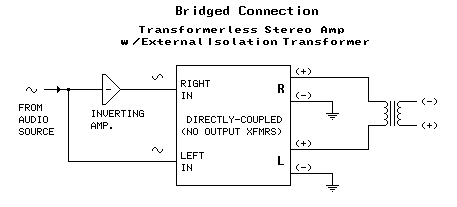 The parallel connection would be appropriate for the situation where the amplifier is producing insufficient current. 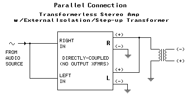 Sorry for the confusion. Max [342] [Thu Nov 22 06:35:56 2018] classe... Thanks for the response. I tried that and had the same results. I found something that might be the solution, but I'd like your opinion on it. In a PDF entitled: "A Class D AM Transmitter for 75 Meters" It says: "This puts the modulation impedance at 56 ohms. The impedance ratio of a transformer is the square of the turns ratio. The voltage ratio is equal to the turns ratio. To properly load the audio amp at 8 ohms the impedance ratio needed is 7:1 or a turns ratio of,√ 7 or 2.64:1. Since our transformer has 115Vac windings a 2.64:1 ratio would mean 115 / 2.64 = 43.28, so a 40V winding would be pretty close. It will be operated in step up and the audio amp would feed the 40 volt winding and the 115V winding would carry the DC for the RF stage and provide the requisite 56 ohms." I'm not sure if this applies to my situation. I'm still confused on what impedance I'm trying to match the audio amp to. Is it 50 ohms? How do I know what the impedance is right at the drain of the mosfet? It's not 50, or is it? Either way, would it be better to use a transformer with the ratio described in the article? [96] [Fri Nov 23 05:23:25 2018] classe... Without knowing the details of your transmitter I can't say what impedance the modulator sees. In the case of the transmitter described on this page, that impedance is roughly 8 ohms. A (probably overly simplified) way to think of it is to divide the RF amplifier's final stage DC power supply voltage by the current drawn by the final. Thus 42V/5.25A yields 8 ohms, so in that case there is little matching required, only isolation. As for what turns ratio to use in your situation, if you know your transmitter's modulation impedance (~ E/I), then the advice you read in the PDF you mentioned sounds like good advice. Max [1673] [Sun Nov 25 21:53:57 2018] classe... I have found the problem! Based on the calculation, the input impedance of my TX should be ~10 ohms, so not too far off. To find the problem, I got hold of an ohm meter that measures in the audio frequency range instead of DC. The problem is that the modulation impedance at 100-300 Hz is only about 1 ohm. At 1 Khz, it is 6 ohms and at 10 Khz, 8 ohms. I tried filtering the bass from my audio signal and that has allowed me to double the modulation power without any problems. I still can't fully modulate though. Why is the impedance so low at low frequencies? Is that just a characteristic of my particular transformer? I tried two different transformers with similar results. So I'm curious why this problem hasn't been encountered before. Is it because I need a certain type of isolation transformer? Thanks for your help! - Paul [910] [Mon Nov 26 06:26:20 2018] classe... Paul, You're welcome! Glad you're making progress! Rather than worry too much about impedance, I think of it in terms of voltage. The modulator under load should be able to produce a peak to peak voltage equal to twice the transmitter's DC power supply voltage. Max [911] [Fri Mar 15 08:52:21 2019] classe... I followed your article with interest and I am very illustrative and you are very attentive. But there is something that surprises me and it still surprises me more than anyone has commented. So I'll pre-order it bluntly. Have you built a square wave emitter? or is that for some reason that I do not know, it becomes a sinus wave. Another question: Why do you insist on not putting fuses directly in DC?, or in other words, why the loss of power destroys the transistors?. Thank you very much: Luis. PS: Sorry for the mistakes, I used the Googe translator [614] [Sat Mar 16 06:32:13 2019] classe... Thanks for your question, Luis. If I'm understanding the question, the answer is yes. The transmitter final amplifier is non-linear: it outputs a square wave (more or less). The transistors act as on-off switches. This is much more efficient than linear amplification. The transmitter final transistors are driven by square waves from the excitor - again, more efficient. (Some class-e builders drive the finals with high-amplitude sine waves. I'm not sure of the reason for that.) The signal is filtered by the capacitor and inductor in the output circuit into a sine wave. My insistence on not fusing the DC is based on my own experience. I destroyed several sets of IRFP350LCs before realizing what was happening. When the fuse blows during a fault it generates a high-voltage transient that destroys the transistors (one or both). Correspondent Yannis (comments above) has discovered several transistor types that are more robust. He has incorporated a DC switch in his transmitter. A switching-type power supply may be less prone to this than the "old-fashioned" power supply in my transmitter. Write again if you have more questions. Max [785] [Mon Mar 18 04:04:21 2019] classe... Thank you very much for responding so soon. Indeed that was my question. The reason why they use sine waves, I think it's harmonic suppression. My experiments with square waves have always generated an excessive amount of harmonics and that is my fear when building your circuit. [298] [Mon Mar 18 05:42:38 2019] classe... For sure you don't want to put square waves out over the air. :) The resonant transformer and output filter effectively prevent that. Max [164] [Wed Mar 20 14:25:21 2019] classe... Your scheme has a drawing of a sine wave on the output. I know that the filters improve the waveform, but I do not know to what extent. Sincerely, I really want to try your design, as soon as I think of how to mount an antenna (I live in an apartment building) I will try it. [301] [Thu Mar 21 07:36:41 2019] classe... Luis, At the frequencies this transmitter operates (long- and medium-wave), getting an antenna to radiate a reasonable fraction of transmitter power will be difficult within the physical constraints of an apartment. Some form of dipole would probably work best and would require an antenna tuner (as would almost any antenna for this band). If your ultimate goal is to broadcast - to operate as a radio station - then FM, with its shorter, more efficient antennas, would be your mode of choice I would think. If you want to participate in amateur radio, then some mode and/or frequency band other than what this transmitter offers would be a better approach. If you just want to fool around and have fun with this thing for the satisfaction of accomplishment (my personal preference), then go ahead and have fun! Good luck! Max [944] [Sun Sep 15 06:30:07 2019] classe... Hi, Max ! Can the formulas given in the article be used to calculate the output transformer for a tube power amplifier? mitchell.steven@usa.com 15.09.2019 [189] [Mon Sep 16 05:30:26 2019] classe... Hi Steven, I assume you're referring to an audio amplifier(?). The only formula that would apply is the turns ratio calculator. If you know the impedance of the output stage, roughly E/I (plate voltage divided by plate current), and the impedance of the load, usually 8 ohms for a typical loudspeaker, then apply the formula given by the calculator: the turns ratio is the square root of the impedance ratio. Max [541] [Thu Sep 10 00:37:01 2020] classe... hmm 1710 is exactly the freq transmitter I need, want to sell it? [79] [Thu Sep 10 11:54:47 2020] classe... No, not wanting to sell it at this time. Sorry. :( Max [83] [Wed Dec 23 19:08:38 2020] classe... Hi Max, I would very much like to read Mallory's paper but cannot find it on the net. Your link to same no longer seems to work. Can you suggest where I might obtain a copy? Great site, with some very useful info. Cheers, Peter VK3CPO (Australia) [290] [Thu Dec 24 05:39:36 2020] classe... Hi Peter, The Mallory article can be found here: http://maxmcarter.com/Classexmtr/simplebeacon/mpm_class_e.html Also here: http://www.ka7oei.com/mpm_class_e.html Thanks for the nice comment on the site! Best regards, Max [13] [Fri Dec 25 21:25:00 2020] classe... Hi Max, thanks for your prompt reply. It's much appreciated. Wishing you and yours a wonderful (Covid free) Christmas. Cheers, Peter [173] [Sun Jan 17 20:54:14 2021] classe... Hi Max, just wondering whether you can tell me what determines the value of the two caps in parallel and between the two output FET drains. Does Mallory's equations take these values into account ?. I have built most of the circuit and testing as I go. The FETs I am using are STW20NM50D (500V, 20A and 214W). I have ordered some STW20N90K5s (950V, 17.5A and 250W) to see how they compare. Cheers, Peter VK3CPO. [461] [Mon Jan 18 09:05:12 2021] classe... Hi again Peter, Mallory's equations, having been derived for a single-ended stage, do not provide for the drain-to-drain shunt capacitors. I found it necessary to include those in order to optimize the stage. (C1 is adjusted, along with the exciter, during tune-up.) The 750 pF value given for C1 refers to a compression trimmer that can be varied over a fairly wide range (~50-750 pF). I should have made that clearer. For a little more on this, refer to the post of Mon Apr 16 08:23:19 2018. Yes, taking it slow and easy at reduced power supply voltage is the way to go on a project like this. If you haven't already, take a look at correspondent Yannis's plywood transmitter. Uses four IRF450LCs driven by two IXDD414 low-side drivers. 98+% efficient. Regards, Max [13] [Tue Jan 19 18:59:20 2021] classe... HI Max, Once again thanks for the advice. The IXD414 drivers could be worth a look. I have been using TC4422 high speed drivers (Microchip) - unlike the IXD414s, these devices do not have tristate outputs. Cheers, Peter [259] [Tue Jan 19 23:04:45 2021] classe... HI Max, once again thanks for the info. I have been using a pair of TC4422s (Microchip) drivers but maybe the IXD414s are worth considering. cheers, Peter [192] [Wed Jan 27 14:54:12 2021] classe... Hello Max, Happy New Year. Question please Sir? Can I reduce the Push-Pull Exciter duty cycle from 50% down to 40-45% with the sym and delay balance pots? Please advise. Thank you, Chris [208] [Thu Jan 28 11:52:46 2021] classe... Interesting question, Chris! I think the answer is no, the exciter as shown can't provide independent 40-45% duty cycle drive signals. For that I think you would need to interpose independant delay circuits, as shown below. Feel free to play with the capacitor values. Reverse the diodes if the duty cycle comes out the "wrong" polarity. 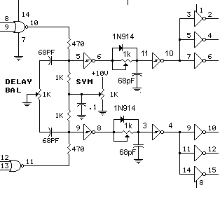 This of course adds some complexity to the circuit and complicates tune-up, but might be well worth the effort. Max [13] [Thu Jan 28 13:08:32 2021] classe... Thanks for the prompt reply and the help Max, I will give that a try. All the best,Chris :) [109] [Fri Feb 19 10:26:27 2021] classe... Greetings, the article is very well written and understandable. But I can't figure out how to wind the primary winding 1.07 μH I am using 4 magnetic ring 14 * 22.5 * hole, 9mm One turn gives 12uH [239] [Sat Feb 20 07:34:11 2021] classe... Thanks for the nice comment. I may not be understanding the question, but.. It appears you're using a core whose AL value (μH/100 turns) is too high. See "Unknown AL Value" above. I suggest using a type #2 (powdered iron) core. The core will be RED in color. Here's a source. Max [13] [Tue Mar 30 18:57:32 2021] classe... desired frequency 3000 kHz inductance will be 0.75 - 0.50 μH ferite, interference suppressing rings 6 pcs., 17.5 * 28.5 * holes 9 mm but it is impossible to create such a primary winding on these tubes, how then do industrial amplifiers work on these tubes? without the use of amidone. [329] [Wed Mar 31 07:42:31 2021] classe... Toroid cores (toroids) are formulated using a variety of magnetic and non-magnetic materials that endow them with different properties, properties that make them suitable for different purposes. Unless a core is marked with some sort of code (like color) by the manufacturer, its properties will be unknown. One property that can be tested for is AL (μH/100 turns). The above article describes a rough test to determine the suitability of the core for the class-e transmitter circuit. The toroids you tested failed the test. They are not suitable. Apparently their AL value is too high. You might try the test again using one core instead of six. (A single core will have an AL value 1/6 the value of six cores.) There may be other properties that make these cores unsuitable. Interference suppressing toroids are usually made of a ferrite material (as opposed to powdered iron) with a relatively high AL value. They are designed to suppress RF energy in a particular frequency range. The material is formulated to be "lossy" in that range; the unwanted RF energy is dissipated as heat in the core. Why would they be used in an industrial amplifier? Possibly for power supply isolation, but I can't say without seeing the circuit diagram and knowing the principles of its design. The humongous T-400-02 core shown in Fig 1 is overkill. A smaller (and cheaper) material-02 core would likely work as well, as correspondent Yannis has shown. A smaller core will have a lower AL value, so the number of primary and secondary turns would need to be re-calculated (or determined experimentally). This calculator relates inductance, number of turns and AL value. I hope this is helpful. Max [712] [Mon Jan 3 05:12:52 2022] classe... Dear Max, My name is Angelos and I made my first attempt to build your pwm transmitter. I tried to keep the cost of the project as low as possible. I was able to obtain 50w carrier with 20V @ 5 Amps and approx. 200W peak. It needs further optimization. Anyway, the reason that I am writing here is because I made two PCB boards for the exciter and the final module with the two mosfeets. I would like to contribute in your try and I would like to send you the files that I created for the PCBs. The program that I used is called "EasyEDA" and I ordered the PCBs from abroad. Is there any way to send you the files (e.g. email) and post them if you wish in order to be available and modifiable by everyone? Thank you in advance. Best regards, happy new year and lots of 73's, Angelos [841] [Tue Jan 4 05:20:41 2022] classe... Hi Angelos, I'm glad you're making progress on the transmitter! I would be happy to receive and post the PCB files. Send to: catradio971@gmail.com Best regards, Max [254] [Thu Jan 6 13:06:20 2022] classe... Dear Max, I am sending you the files of the PCB designs that I made on EasyEDA as I promised. I am not an expert on making PCBs but the files I attach work well for me. I ordered the PCB boards from JLCPCB and I was pretty satisfied with the quality. Since I do not wave a signal source with more than 4Vpp to drive the exciter, I included a simple 2 transistor amplifier in front of the CD4013 (or CD40106 in my case). I am sure that the designs need further optimization but I think it would be very helpful for someone to start with the construction of the transmitter. I also attached a photo from my final assembly. Feel free to make any changes if you wish! Best regards and greetings from Greece! Angelos Ntimtsas P.S. In case that there is a problem with the format of the attached files, please let me know. [912] [Thu Jan 6 13:41:55 2022] classe... Thanks Angelos, that is is a very nice looking transmitter! I have incorporated the files on a page, along with the text of your email and address, in case anyone wants to communicate with you about the project. Thanks again and Best Regards, Max [See Angelos's transmitter files here.] [312] Scroll up ↑ to view previous comments. Add Your CommentType your comment or question in the box below and click SEND.
|
