Characterizing the Antenna
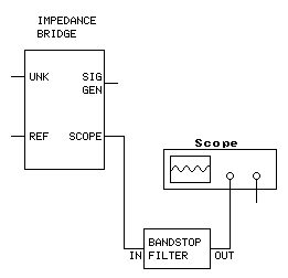
This method uses a signal generator, oscilloscope and impedance bridge. (See "Building an Impedance Bridge" below.) A spectrum analyzer, frequency-selective voltmeter or S-meter equipped receiver could be used in place of the oscilloscope. A spectrum analyzer equipped with a tracking generator can replace both the oscilloscope and the signal generator. You will also need a multimeter and a capacitance meter.
- Connect the test equipment to the antenna as shown below. Connect the UNK test cable ground to the antenna grounding system (ground radials) or the counterpoise in the case of a balanced antenna (dipole). If the antenna includes a feedline, connect the test equipment to the feedline at the feedpoint (the near end) where the transmitter would normally be connected. (The signal generator, oscilloscope and REF are grounded through the test cable shields and case of the impedance bridge.)
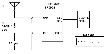
- Adjust the signal generator to the operating frequency at maximum or near maximum output amplitude (avoid clipping).
- Adjust the reference potentiometer for a dip. The dip will be sharp and narrow. You may have to vary the signal generator frequency to find it. (A nearby AM broadcast station can make this test difficult. See "Optional Bandstop Filter" below for a fix.) If a dip can't be found, replace the 100-ohm potentiometer with a 1000-ohm potentiometer and try again. Repeat as necessary to obtain the deepest dip. Do not disturb the potentiometer setting after the dip has been found.
- If you obtain total nulling, with no residual signal present (ie, flatline), then the antenna impedance is non-reactive - purely resistive - at that frequency. Measure the resistance of the potentiometer to obtain the impedance.
Z = R
where:
Z is the antenna impedance
R is the measured resistance of the potentiometer in ohms.
- If you are not able to obtain a total null, leave the potentiometer undisturbed and proceed to the second pass.
Second Pass - find the reactive component (capacitive)
Antennas shorter than ¼ wavelength (½ wavelength dipole) tend to have residual capacitive reactance.
- Connect a variable capacitor (~500 pF)* in series with the potentiometer, as shown below (test lead grounds remain connected):
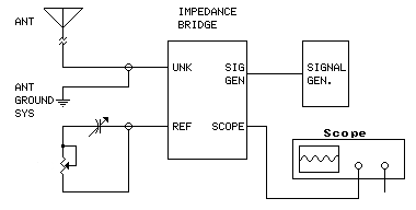
*Tuning capacitor from an old radio (sections wired in parallel).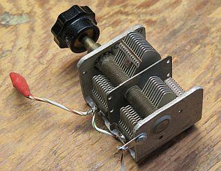
- Adjust the variable capacitor to obtain the deepest possible null. You may have to slightly readjust the potentiometer.
- If you obtain a flatline, the antenna impedance includes a negative reactive component (capacitive). Measure the potentiometer to obtain the resistive component. Measure the test capacitor to obtain the capacitance. The reactive component is calculated as follows:
Xc = 1/(2πFC)
where:
Xc is the capacitive reactance in ohms,
F is the operating frequency in Hz, and
C is the measured capacitance in farads.
The antenna impedance is:
Z = R - jXc [complex number]
where:
Z is the antenna impedance
R is the resistive (real) component in ohms and
Xc is the reactive component in ohms.
The antenna's absolute impedance is:
|Z| = √R2 + (Xc)2
where:
|Z| is the absolute impedance in ohms.
- If you are not able to obtain a total null, leave the potentiometer undisturbed and proceed to the third pass.
Third Pass - find the reactive component (inductive)
Antennas longer than ¼ wavelength (½ wavelength dipole) tend to have residual inductive reactance.
- Reconfigure the test setup with the test capacitor connected between the antenna and the UNK bridge port, as shown below (test lead grounds remain connected):
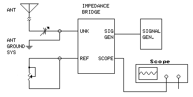
- Adjust the test capacitor to obtain the deepest null. You may have to slightly readjust the potentiometer.
- If you obtain a flatline, the antenna impedance includes a positive reactive component (inductive). Measure the potentiometer to obtain the resistive component. Measure the test capacitor to obtain the capacitance. The reactive component is calculated as follows:
XL = 1/(2πFC)
where:
XL is the inductive reactance in ohms,
F is the operating frequency in Hz, and
C is the measured capacitance in farads.
The antenna impedance is:
Z = R + jXL [complex number]
where:
Z is the antenna impedance,
R is the resistive (real) component in ohms and
XL is the reactive component in ohms.
The antenna's absolute impedance is:
|Z| = √R2 + (XL)2
where:
|Z| is the absolute impedance in ohms.
Building an Impedance Bridge
The Bridge Circuit
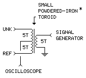
The ground connections for REF (reference), UNK (unknown) and oscilloscope are not shown. The circuit's aluminum enclosure forms a common connection point for all grounds.
Bridge Inside
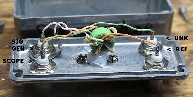
The windings are made by first twisting the three wires together into a cable, then winding 5 turns of the 3-wire cable on the core. White = GEN, brown = REF, green = UNK, brown/green (twisted) = SCOPE. [This method of winding is called "trifilar".]
*The core is green/blue, which is iron powder material 52. I don't think the particular core material makes much difference in this application, but it probably should be a powered iron mix rather than a ferrite. If I'm reading the specifications correctly, the 52 mix should be useful up to 100 MHz. I found this core in my junk, as I did the aluminum box, which had connectors pre-installed by someone. [Almost all components for this project came from the same source - junk.]
Bridge External
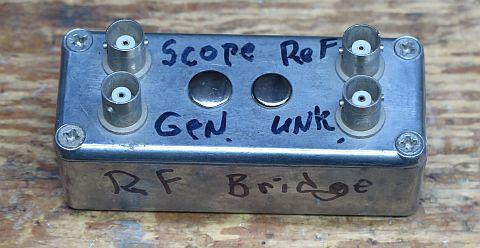
Equipment grounds are interconnected via the common case.
Test Leads
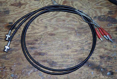
The test leads for REF and UNK, constructed with RG-58 coax, are made the same length. This cancels cable reactance. Leads for GEN and SCOPE, made with coax cable terminated at both ends with BNC connectors, can be any length.
Optional Notch (Bandstop) Filter
If your antenna is within a couple of miles of an AM broadcast transmitter, signal pickup from the transmitter can obscure the test signal on the scope, making it difficult to see a null. Including a notch filter in the test setup, tuned to the broadcast transmitter's frequency, will make life easier.
1340 kHz Notch Filter Example
Circuit assumes 1 megohm scope input impedance.
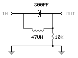
Design calculations:
L ≅ 400/(2πF)
C ≅ 1/(2π400F)
- F is the desired notch frequency in Hz.
- For the lowest and deepest notch - ie, the highest circuit Q - use the lowest resistance inductor available.
- Use a variable capacitor or inductor to allow fine adjustment to a specific frequency.
As-built 1340 kHz Bandstop Filter
Inside
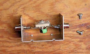
The capacitor in this filter is adjustable.
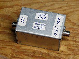
Outside
back
