I recently read a book by Erik Larson called Thunderstruck. It's about Guglielmo Marconi and his efforts to develop and establish wireless telegraphy in the late 19th and early 20th century. It brought back memories of me as a boy when I first saw, in an old Compton's Pictured Encyclopedia, the schematic layout of an early spark transmitter. I was inspired! It looked so simple! I had visions of winding induction coils and building coherers. Well, it wasn't simple, and I never had sufficient fire in the belly to come even close to building a "Marconi set". Now, years later, I was re-inspired and decided go ahead and build a spark transmitter just for fun.
Narrowband/Shortwave Vision
Marconi envisioned commercial applications: He was looking to make lots of money. His vision was eventually realized in a big way after a couple of incidents - a world-wide front-page mystery murder case in London and the sinking of the RMS Titanic in 1912 - finally brought the practical benefits of this almost magical technology to the general public's full attention. My vision was different. I would build this thing strictly for fun, but also wanted to end up with something that works well. I was not interested in a restoration or in building a replica of anything. Marconi himself might not recognize it.
Wireless in the early days had problems - the pioneers of the technology were working with brand new concepts after all. Marconi's early efforts were confined to the longwave portion of the spectrum (>500m wavelength). At the time it was thought that shorter wavelengths were not useful for long-range wireless communications. 1000-mile range was possible but required enormous power. The other problem was the excessive bandwidth occupied by the emissions of those early transmitters. They were bandwidth hogs. A powerful transmitter could wipe out an entire band for hundreds of miles. To address those concerns, I wanted my transmitter to (1) have its transmitted bandwidth somewhat restricted, and (2) operate well up in the shortwave portion of the spectrum where world-wide propagation is the norm.
Limiting Bandwidth
The signal emitted by a typical spark transmitter looks something like this:

It's a train of damped waves and sounds over the air like a buzz or whine. The multiple waves are created by the multiple openings of the primary interrupter on the induction coil that produces the high voltage for the spark (usually several hundred times per second). How fast the wave decays is a function of the Q of the resonant circuit formed by the antenna and ground system and the spark gap circuitry. The higher the Q of the system the longer the decay time and the closer the wave comes to being continuous (the origin of the abbreviation "CW", for "continuous wave"). Since power is applied more or less instantaneously (each time the spark jumps the gap) but is withdrawn from the circuit continuously via circuit losses and radiation from the antenna, the result is necessarily damped. The radiated signal has both amplitude- and phase-modulated components and as such produces multiple sidebands extending either side of the nominal operating frequency.
The most obvious way to limit the bandwidth of an AM signal is to reduce the modulating frequency. In the case of a spark transmitter, the modulating frequency is the spark's repetition rate. So, instead of hundreds of damped waves per second, the envisioned transmitter would emit only a few - maybe one to eight per second. This doesn't leave much capacity to transmit information, but is sufficient since the envisioned transmitter would function only as a beacon. The transmitted clicks would sound somewhat like Morse code "dots". A train of, say, three clicks, followed by a pause, would sound like a Morse letter S. [The 'S' is historic. Marconi's first successful trans-Atlantic wireless transmission supposedly was a series of Ss.]
The second way to limit bandwidth is to provide filtering between the spark generator and the antenna. The transmitter's "tank", in this case the reactive components (capacitors, inductor, antenna) in Figure 2 below, form a fourth-order filter with a bandwidth (depending on the circuit's Q) narrow enough to suppress higher-order sidebands and harmonics. This is not at all a new concept. The notion of the tank, or tuned circuit, was developed early on.
The Circuit
The spark transmitter is made up of three parts: a high-voltage power supply which provides up to 25 thousand volts DC to power the spark (Fig. 1); the spark transmitter proper (Fig. 2); and an optional spark counter (Fig 3).
Figure 1
High-Voltage Power Supply

The power supply consists of an oscillator/driver circuit, step-up transformer and voltage multiplier circuit. The transformer is operated in resonant (class-e) mode. The frequency [FREQ] and symmetry [SYM] controls in the oscillator circuit provide a means of optimizing the efficiency of the transformer. The adjustments are made by listening to the transmitter spark and adjusting to maximize its repetition rate (this corresponds to maximum power supply output voltage). The output of the transformer secondary is a nearly pure AC sinewave at about 15 kHz with a peak-to-peak amplitude of 5-7.5kV (depending on load). The voltage multiplier rectifies and steps up the secondary voltage to negative 25 kV DC. The output voltage is set by the kV ADJ control. A low on pin 4 of the 555 switches the power supply to the off state.
Oscillator/HV Transformer
The transformer core was added and the completed assembly mounted on the oscillator board.
Voltage Multiplier
The capacitors are .0047 µF / 10 kV ceramic units from HVStuff. The diodes are 6 kV, 200 mA units All Electronics #R6000.
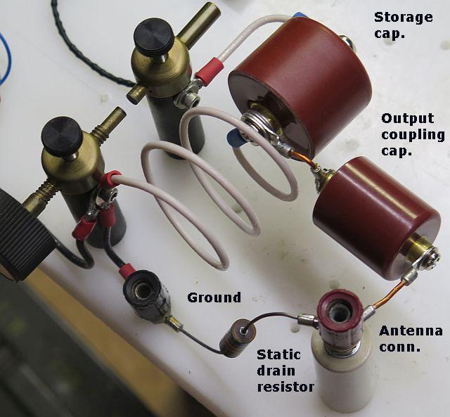
Figure 2
Transmitter
(11 MHz)
|
Notes:
|
The transmitter circuit consists of a 10-megohm charging resistor, 1000 pF energy storage capacitor, spark gap, .21 µH inductor and 165 pF output/antenna tuning capacitor. The storage capacitor is charged by the high-voltage power supply through the 10M resistor and inductor. When the voltage gets high enough, the air between the spark electrodes ionizes and becomes conductive - virtually a dead short. The storage capacitor discharges through the gap and inductor, dumping part of the stored energy into the antenna. The transmitter components are mutually resonant at about 11 MHz and, like a struck bell, ring for several cycles. The number of cycles is determined by the Q of the system, which appears to be around 5; in other words, the decay time is about 5 cycles. About 90% of the capacitor discharge energy is delivered to the antenna. The 47k resistor discharges static buildup.
After the spark extinguishes, the cycle begins again. The circuit's repetition rate is determined by the combination of the kV setting of the HV power supply and the spark gap setting. A larger gap requires a greater voltage to arc and thus a longer charge time which produces a slower rep rate. Conversely, a higher voltage setting shortens the charge time, producing a faster rep rate.
The 22k resistor and .01 µF capacitor connected between ground and power supply common (com) provide a 20-volt, negative-going pulse during every storage capacitor recharge cycle. The pulses are counted by the spark counter circuit described below.
10 Megohm Charging Resistor
The resistor is made up of 10 1-meg ½-watt resistors connected in series and insulated with heat-shrink tubing. It's connected from the output of the voltage multiplier to the hot end of the energy storage capacitor and spark gap electrode.
Energy Storage Capacitor
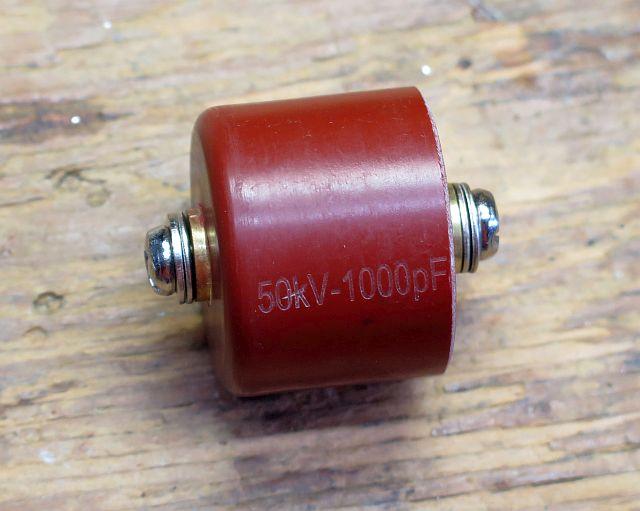
This capacitor, a 1000 pF 50 kV ceramic "doorknob" type, is at the heart of the transmitter. The capacitor is specified by the vendor to have a series inductance <.025µH and Q >250 at 11 MHz. A similar type capacitor (165 pF) forms the output coupling and antenna tuning side of the circuit. From HVStuff.com.
Spark Gap
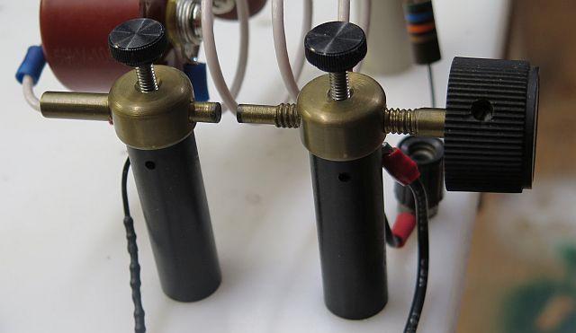
I've no idea where this came from originally. It came to me as part of what looked like a Tesla coil. I haven't figured out a direct way to measure the current through this gap when it fires, but, given the observed decay time of the generated pulse, it's in the neighborhood of 1500 amps. Current flows for about 250 nS before the arc extinguishes and the circuit goes open.
Transmitter Circuit
The coil has a nominal inductance of .21 µH.
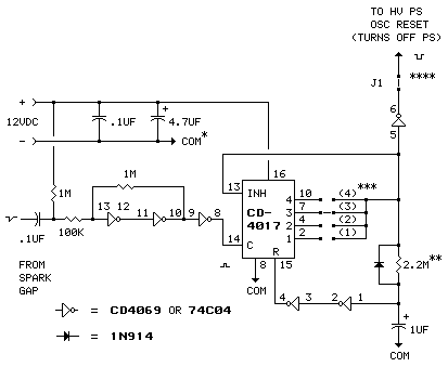
Figure 3
Spark Counter
| *Do not ground the negative 12-volt power rail. (Also verify external 12-volt power source is ground isolated.) |
| **Resistor value sets pause time. 1 megohm ≅ 1 second. |
| ***Jumper position sets spark count. Install one jumper only. |
| ****Remove jumper J1 to disable counter. |
The CD4017 counter chip can accommodate counts up to 9. See datasheet.
The counter circuit is not necessary for the transmitter to function; it only adds a bit of identification to the outgoing signal. As shown, the spark counter adds a pause of about 2 seconds after every 3 sparks. If the spark counter is not used, the 22k resistor and .01µF capacitor on the positive spark gap electrode are not required. The electrode would be connected directly to the common terminal (com) of the power supply, as shown in Fig 4 below:
Figure 4
Power Supply/Gap Connection
if the spark counter is not used.
Spark Counter, As-Built
The counter piggybacks on the PS oscillator/xfmr board.
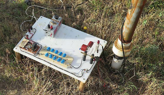
The As-built Transmitter
The white board is ½" thick and made of an easily-drilled plastic of some kind. It may have originally been a cutting board.
Antenna
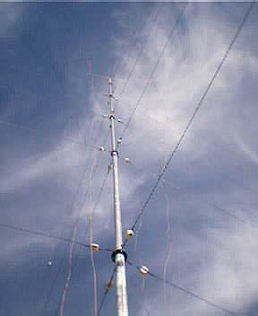
This is a 50' TV antenna mast with a 6-foot length of aluminum tubing added at the top, giving it a total height of 56' (17m). The mast is insulated at the base with PVC water pipe and the guys are insulated at both ends with porcelain electric fence insulators. There are eight 141' (43m) insulated radial wires buried just below ground. I built it 25-30 years ago to operate in the longwave portion of the spectrum. It has a large drooping top hat (not easily seen in the photo) incorporated in the top level of the guying system, and four "down wires" (which can be seen in the photo). Even with the extensive top hat, etc, the antenna required a huge base loading coil to bring it into resonance at those frequencies (160-190 kHz). Some years later it was used on the medium-wave AM broadcast band. Physically it's 5/8 wavelength in height at 11 MHz. Electrically, it resonates (120 ohms resistive, zero residual reactance) at about 10.7 MHz. [120+j87 @ 11.0 MHz.] (If you're interested in how the antenna was characterized, click here.)
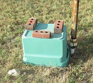
Transmitter at the base of the antenna.
A laundry basket keeps the weather out.
Incredible Numbers
When charged to 20,000 volts, the storage capacitor holds 0.2 watt-seconds of energy. Released over a time period of about 15 nS (1/2πF) the capacitor dumps about 13e6 peak watts (thirteen million watts!) into the spark and circuit components. The
circuit rings for about 250 nS, spreading the power out to about 800,000 peak watts. About 10% of the energy is dissipated in the heat, light and sound generated by the spark, with about 90%, 720,000 peak watts, delivered to the antenna (actual measurement with an oscilloscope). If the ciruit uses a GDT instead of an air gap, peak power increases slightly. At 25 kV DC input, peak output power increases to over a million watts.
Scope Shot
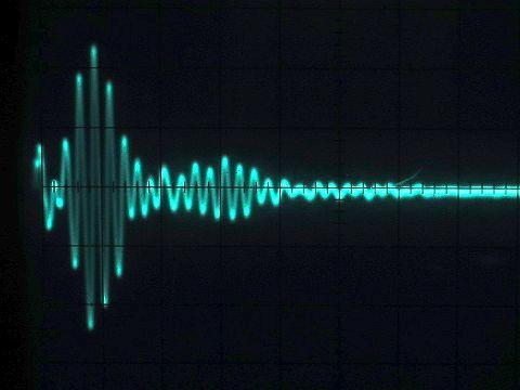
500 nS per major horizontal division. Rep rate about 4 pulses per second. (The photo is an eight-second time exposure.)
So, How Well Does it Get Out?
The operating frequency, height of the antenna and calculated power delivered to the antenna suggest it might be heard world-wide, but I don't know that for a fact. Listening with a SW receiver equipped with a very short antenna (14"/35cm) located approximately 1 ¾ wavelengths (47m) from the transmitting antenna, well beyond the transmitter's near field, it can be heard on just about any frequency within +.5 and -1.5 MHz of the transmitter's nominal frequency. The S-meter barely flickers (USB mode, AGC set to 'FAST'). At the same location the same 14" antenna connected directly to the input of an oscilloscope displays about 1 volt peak-to-peak (above photo). Increasing the length of the antenna to 4 feet increases signal pickup to about 10 Vp-p. Touching my finger to the scope input produces about the same voltage. [I make a pretty good antenna, apparently.]
This suggests that, while total power in the pulses might be impressive, it's an extremely wideband signal - much less power is present on any particular, say 5 kHz, channel. In other words, the sparker is sending a very crude form of spread spectrum. The signal has a very subtle sound and, if not for the 3-click/delay format, would be indistinguishable from nature's own spark transmitter, distant lighting. Interestingly, at this close range anyway, the receiver's noise blanker, when enabled, is 100% effective in knocking out the clicks from the transmitter.