Twist-Shift Keying could also be called
Rotation-Shift Keying, Orthogonal BPSK, Polarization Modulation or Twist Modulation.
|
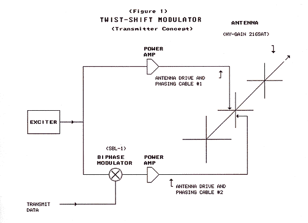
This article presents a novel modulation method. It's a way to transmit and receive data using the rotation, or "twist" of a circularly polarized wave. We've implemented the idea in the 2-meter VHF band using some surplus land-mobile equipment we had on hand. Based on the results of tests with our system, we think the method would be useful in situations where reflections and other transmission path anomalies might compromise conventional signaling modes. We've been calling it "Twist-Shift Keying". DESCRIPTIONTRANSMIT:Twist-Shift Keying requires an orthogonal antenna at the transmitting end of the communications path. Orthogonal means that there are two drive elements crossed at right angles and mutually perpendicular to the direction of transmission. When properly driven, this type of antenna produces a rotating, or circularly polarized (CP), wave front. The two transmitting antenna elements must be driven in quadrature in order to produce a CP wave front. This can be accomplished either mechanically, by offsetting the antenna elements 1/4 wavelength in space along the axis pointing in the direction of transmission (longitudinal, or Z-axis), or electrically, by driving the crossed elements 90 degrees out of phase. The direction of rotation, or "twist", of the wave front (clockwise or counterclockwise) is determined by the relative phases of the two drive signals. If the X-plane drive signal leads the Y-plane signal, the wave front rotates in one direction. If the Y-plane drive signal leads, the wave front rotates in the other. One drive method that lends itself to Twist-Shift Keying is to utilize two transmitters simultaneously driven by a common excitation oscillator. Each transmitter is connected to one of the driven orthogonal elements. The 90-degree phase offset, if needed, can be produced simply by increasing by 1/4 wavelength the length of the transmission line connecting one of the transmitters to its driven antenna element. (The added transmission line can be placed at any point in the transmit signal path, either internal or external to the transmitter.) The CP signal is twist modulated, or "Twist-Shift Keyed", by reversing the twist of the wave front. This is accomplished by reversing (shifting by 180 degrees) the phase of one of the antenna drive signals. The 180-degree phase shift can be produced either internally in one of the transmitters at some low level intermediate stage, or externally between one of the transmitters and the antenna. An alternate method might be to shift the antenna drive signals 90 degrees in opposite directions (+90 degrees and -90 degrees). Several techniques for generating the 180-degree phase shift have been suggested. One method incorporates a data-driven active phase-shift/inverter stage in one of the transmitters. A second method uses a multiplier such as an exclusive-OR gate or analog biphase modulator in the signal path of one transmitter. A third technique uses the transmit data to alternately switch in and out a 1/2-wavelength delay line in the signal path in one transmitter. We have successfully demonstrated signaling rates in excess of 2 kb/s using the second technique with a pair of surplus Motorola SyntorX VHF land-mobile FM transceivers, with a MiniCircuits SBL-1 mixer acting as the phase modulator.
Figure 1 illustrates the concept at the transmit end: |

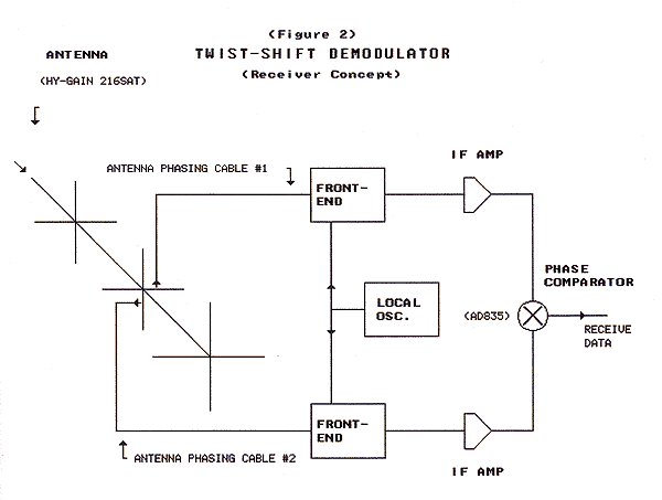
RECEIVE:Requires an orthogonal antenna at the receive end of the communications path. The signal outputs from crossed antenna sections at the receive end must be "normalized", that is, brought back to 0-degrees phase offset. This can be accomplished either mechanically, by offsetting the antenna elements by 1/4 wavelength in space along the axis pointing in the direction of transmission (longitudinal, or Z, axis), or electrically, by delaying the signal from one set of elements 90 degrees. One method that lends itself to the reception of Twist-Shift Keying is to utilize two synchronized receivers - that is, receivers sharing a common local oscillator - each driven by one set of antenna elements. The phase normalization, if needed, can be accomplished by increasing the length of the transmission line connecting one of the receivers by 1/4 wavelength. The extra cabling can be added either internally or externally to the receiver. In a real-life situation it will most likely be necessary to provide some way to 'fine tune' the delay in order to perfectly normalize (optimize) the receiving system. Data recovery is accomplished by multiplying the two outputs of the receivers at some point before the final (stock) detectors. The multiplier can be one of two types: amplitude limited or non-amplitude limited (linear). The linear type should produce better results at slow data rates (when followed by appropriate data filtering). We have successfully demonstrated the non-amplitude limited case using another pair of Motorola VHF transceivers with an Analog Devices AD835 multiplier acting as the phase detector. After detection, the output data must be filtered by a suitable filter and interfaced to the receive data communications equipment. Figure 2 illustrates the concept at the receive end: |

TWIST-SHIFT RATIONALECP BACKGROUNDThe term polarization diversity probably better describes circular polarization (CP) systems. The typical polarization diversity (non Twist-Shift) receiving system is sensitive to both the X and Y field planes. The antenna gathers a signal voltage from both planes and adds them together. The output of the antenna/receiver is the vector sum of the two planes. The aim of such a system is to produce the maximum signal output, regardless of its polarization. Perfect circularity (of the radiated signal) actually is a special case, being tough to produce from a ground-level transmitting antenna not aimed at space. Reflections from the ground and other objects degrade the signal from the ideal. Perfect circularity in the receive antenna is likewise a special case. Fortunately, perfect circularity is not a requirement for the success of either typical polarization diversity or the Twist-Shift Keyed receiving systems. A normal CP (polarization diversity) transmission system is degraded when the rotation of the incoming signal is opposite that of the 'twist' of the receiving antenna, and falls flat in the special case of a perfect CP signal rotating in one direction arriving at a perfect CP receiving antenna twisted in the opposite direction. That situation creates the 30 dB (or greater) loss of sensitivity noted in antenna texts. A designer or user of a polarization diversity system must take that fact into account, either by specifying a non-CP receiving antenna or by making sure the twist of the receiving CP antenna matches that of the received signal.
HOW TWIST SHIFT DIFFERSIn the Twist-Shift receiving system, the absolute direction of rotation (CW/CCW) is immaterial. The receiver is sensitive to both directions of rotation. At the receiver the phases of the two wave front planes (X and Y) are compared to determine the direction of rotation. The system assigns rotation in one direction the value "1" and rotation in the opposite direction the value "0". The receiving system could be thought of as being temporally differential. It is (ideally) not interested in the absolute or relative amplitudes of the received X and Y signals. It only wants to know the phase difference, and even then not the actual value of the difference, only whether one signal leads or lags the other. Nothing is perfect, and a practical Twist-Shift receiver is no exception. Cross-polarity discrimination performance on the order of 20 dB should be achievable at the receive end using only cut-and-try. Better performance - 30 or 40 dB - requires the ability to fine-tweak the system using some sort of phase balance control. However, super-good cross-polarity performance is not strictly necessary. As stated above, an ideal detector will be insensitive to amplitude differences and will operate quite satisfactorily under adverse conditions of degraded circularity.
RATIONALE CONTINUED - WHY TWIST-SHIFT?SELF-DEMODULATINGSince there is no need to regenerate the modulating carrier at the receive end, no special carrier recovery circuitry is required. All that's required to convert to any particular signaling rate is to set the data filter at the receive end to the appropriate bandwidth. Phase-locked loops (PLLs) or other techniques are not needed since the transmitted signal brings along the demodulating carrier. This becomes significant when 1) the carrier frequency is relatively high (VHF in this case), 2) the bandwidth is narrow, 3) the signal-to-noise ratio is low, and 4) the transmission path is subject to reflections and atmospheric perturbations. Synchronous data transmission under low S/N conditions using carrier regeneration techniques (single sideband) requires both the modulating carrier source at the transmitting end, and the demodulation carrier source at the receive end, to be very stable, about an order of magnitude more stable than the carrier period divided by the signaling rate. Twist-Shift, which transmits the rotated carrier along with the data, eliminates the need for high-stability frequency sources.
TOLERANCE FOR PATH ANOMOLIESThis is conjecture on our part and is yet to be proven, but early results of our tests suggest this might be the real advantage of the Twist-Shift methodology. PROBLEMSWAVE-FRONT DISTORTIONObjects encountered in the signal path can distort the circularity of the wave front causing one plane to be affected differently from the other. This degrades the performance of the receiver-detector and could make Twist-Shift keying unsuitable for terrestrial communication at some frequencies and under some circumstances. However, we have observed that a practical system can reliably decode the received Twist-Shift data under very degraded conditions. COHERENT INTERFERENCEThis could come in the form of an on-channel interfering signal received by the antenna system, or cross talk from some source internal to the radio receiver/s - such as the local oscillator synthesizer. Carefully balancing the system (antenna, cables, receivers, and detector) should minimize the effect of external interference. The Motorola SyntorX VHF radios we have used for our experiments are well shielded and we've encountered no problems with internal signal cross talk. The design of the data filter can also minimize the effects of coherent noise. Any coherent interfering signal will show up at the output of the detector as a DC offset. The filter (or subsequent voltage comparator) should be designed to be insensitive to DC offset. It should be AC-coupled in other words, having a high-pass response appropriate to the selected signaling rate. RECEIVER SATURATIONAnother fly in the ointment could be saturation of the radio receivers. The voltage recovered from one of the radiation planes may be strong enough to swamp the voltage from the other, or an on-channel foreign (interfering) signal may saturate one or both receivers, causing the desired signal to be swamped. Again, balancing the receiving system to as near perfect circularity as possible should minimize these effects, but probably cannot completely eliminate them. In the case of an on-channel interfering signal, the remedy would be to change channels. Schematics produced with DCCAD. Click here to see an IMPLEMENTATION
|