Power Ultra-Brights in Series
High-Power LED Series-String Power Supply
Max Carter
If your lighting or decorative application calls for multiple high-power (ultra-bright) LED (Luxeon, Cree, etc.) you might be interested in this power supply circuit. The DC supply presently energizes a series string of 50 high-power LEDs on a decorative holiday star (LED-Illuminated Star). It was developed experimentally using (mostly) surplus parts. It will power up to 90 (depending on color) ultra-bright LEDs in series at currents up to 1.25 amp. Its flexibility (adjustable voltage) has been especially useful as the number of ultra-brights in the star project has grown from 15 to 50 over several years.
Why series?
Ease of active current regulation is the main reason. With LEDs connected in series, the same current flows in all LEDs in the string. One current regulator can serve them all. The series configuration also allows LEDs of different colors to be mixed within the string. With a voltage-adjustable power supply, a series string can be as flexible as a parallel configuration, allowing as few as one LED, up to the maximum number the supply can handle. Wire size is a secondary consideration. The interconnecting wire for a series string need be sized to handle only a fraction of an amp (typically), whereas the parallel configuration may require wire (and power supply) sized for tens of amps.
Power Supply Design Objectives
The prime requirement was that it be adjustable from near 0 to a couple of hundred volts DC, giving it the ability to power multiple ultra-brights in series. Also, that it be current regulated: Some of the LEDs in the string the PS was intended for are independently shunt flashed. Current regulation keeps the current (and thus LED light output) constant under the varying load caused by the flashers. I also wanted the circuit to be reasonably efficient and (to contain out-of-pocket costs) use parts on hand and surplus parts from my junk pile. The resulting supply is a bit unconventional but does meet all of the requirements. Notice that isolation was not one of the requirements. The power supply is not isolated from the power line.
Here's the as-constructed circuit, followed by a description.
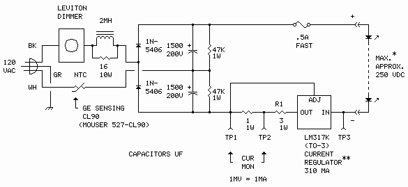
**Alternate current regulator ↓ or no regulator ↓
Circuit description
Leviton dimmer
The dimmer sets the operating voltage of the power supply. The dimmer varies the firing time - the "firing angle" - of a triac. (A triac can be thought of as two paralleled silicon control rectifiers of opposite polarity sharing a common gate.) The output of the dimmer, instead of being a steady sinewave, is a series of pulses at the line frequency of varying width (ON time). When the dimmer is set to maximum the output pulses will have maximum ON time; the full AC sinewave will appear at the output. When set to minimum the pulses will have minimum ON time, or no ON time at all. The pulses are integrated into a (more or less) steady voltage by the energy-storing components (inductor, capacitors) downstream from the dimmer.
I found the Leviton dimmer in my junk pile. parts sources
Rectifier Diodes
The diodes direct the pulses from the dimmer to charge the 1500 uF capacitors. The two capacitors are charged alternately during the AC input cycle: The top capacitor is charged during the positive half of the cycle, to about +130 volts DC (max); the bottom capacitor is charged during the negative half, to about -130 volts DC (max). Since the two capacitors are connected in series, the voltages add, to about 260 volts (max).
Instead of the two 1N5406 diodes shown, the as-built power supply actually uses a bridge rectifier liberated from a failed computer power supply connected as a half bridge. parts sources
2 mH choke, 16-ohm 10-watt resistor, NTC thermistor, 1500 uF capacitors and 47k resistors
These components form a second-order network that serves as a "flywheel" that integrates the pulses from the dimmer. The time constant of the LC network (inductor and capacitors) is a significant fraction of the period of the applied AC line voltage, resulting in a lag, or inability to respond instantaneously to changes in applied voltage. The result is a nearly constant voltage on the terminals of the 1500 uF capacitors (and some power factor improvement on the AC line). Wider dimmer pulses produce a higher voltage; narrower pulses produce a lower voltage. The actual voltage is also somewhat dependent the load connected to the capacitors (the LED string). The voltage can be varied from near zero to about 260 volts DC.
The 16-ohm 10-watt resistor dampens ringing in the choke caused by the abrupt switching of the dimmer, making it look less reactive. The high-voltage inductive kick produced by the choke on each half-cycle could damage the dimmer otherwise (the dimmer is specified for use with incandescent loads).
The NTC (negative temperature coefficient) thermistor limits component-damaging surge current when power is first applied. When cold the NTC has a resistance of around 100 ohms. When the NTC is hot - heated by the current passing through it - the resistance drops to a couple of ohms.
The 47k resistors are bleeders. They slowly discharge the capacitors after power is removed. The slow bleed rate allows the NTC to fully cool by the time the capacitors are completely discharged.
The 2 mH choke, a high-current/low-resistance model (<0.1 ohm DC resistance), was found in my junk pile, as was the 16-ohm 10-watt resistor. The 1500 uF capacitors came from a failed computer power supply. The NTC thermistor was ordered from Mouser Electronics for a couple of bucks. The 47k resistors were new from old stock. parts sources
LM317K linear voltage regulator, 3-ohm and 1-ohm 1W resistors
The LM317K acts as a current regulator. The 1-ohm and 3 ohm (R1) resistors sense the current through the LEDs. Higher current produces a higher voltage drop across the resistors. The sensing input (ADJ) of the LM317 is connected across the resistors and acts to keep the voltage drop, and thus the LED current, constant. Additionally, the 1-ohm resistor allows monitoring of the LED current. The combination of the two current sensing resistors produces a regulated current of 310 mA through the LEDs.
The LM317K and resistors came from new stock on hand. I found the heatsink for the LM317 in my junk. parts sources
back ↑
back ↑
The power supply adjustment procedure starts below the photos.
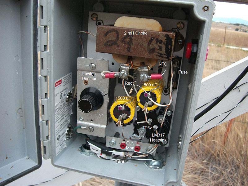
Photos
The power supply is installed in a water-tight plastic box, also from the junk pile.
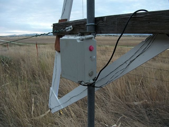
The power supply mounted.
Adjustment
Use caution when making adjustments. The circuit is not isolated from the power line.
Potentially lethal voltages are present.
With load (LED string) connected and power not applied:
- Set dimmer to minimum (fully CCW).
- Set multimeter to read millivolts DC; connect multimeter probes to TP1 and TP2; power the circuit.
- Increase the dimmer setting (turn CW) slowly until no further increase in current is noted on the multimeter (indicates circuit is regulating). Note: The scale factor is 1 mV = 1 mA.
- Set multimeter to read volts DC; relocate multimeter probes to TP1 and TP3; verify voltage reading of 5-10 volts (10-15 volts for OKI-78SR-3.3/1.5-W36H-C); re-adjust dimmer if necessary to meet this requirement.
- Remove multimeter probes.
- Verify all LEDs in string are lit.
New Parts Sources
The power supply described on this page was constructed mostly with scrounged junk, but could also be built using new parts. Here are some suggested sources:
| Part: | Suggested Suppliers: |
| Leviton dimmer | "Leviton" is a brand name. Any incandescent dimmer would probably work. These are available at hardware stores and home improvement centers. Home Depot R50-06602-0IW, for example. |
| 2 mH choke | Digikey 817-1676-ND, smaller and lighter than the one shown, would likely work. |
| 16-ohm, 10-watt resistor | Digikey 16W-10-ND |
| 1N5406 diodes (2) | The specified diodes are available very cheaply from many suppliers. Futurelec 1N5406, for example. (They're a tad slow; allow a couple of weeks for delivery.) |
| Capacitors (2) 1500 µF/200 V. | Digikey 493-2531-ND |
| 1-watt resistors: 47k (2), 1Ω, 3Ω | Digikey PPC47KW-1CT-ND, PPC1.0W-1CT-ND, PPC3.0W-1CT-ND |
| NTC thermistor | Mouser Electronics 527-CL90 |
| LM317K regulator/heatsink | Futurelec LM317K (also suggested heatsink) |
| Murata DC/DC converter | Amazon Murata OKI-78SR-3.3/1.5-W36H-C |
| Weatherproof box (if needed) | Amazon has dozens listed under "Plastic Outdoor NEMA Box" |
Schematics produced with DCCAD.
