These adjustments are for an MPX96 transmitter equipped with modifications 1-6 described here.
- Place a jumper from the junction of R28 (470 ohm) and R29 (47k) to ground. This puts a short circuit around R28 (470 ohm) and kills the 19 kHz pilot.
- Remove any and all audio input signals.
- Connect an oscilloscope to TP4 (IC1-pin 1). You should see the 38 kHz subcarrier.
- Adjust R15 BAL (10k) for MINimum subcarrier level. You should be able to completely null the subcarrier.
- Connect the scope (or an RMS voltmeter) to the junction of R7 (22k) and R5 (22k).
- Feed a 1 kHz audio tone at 0 VU (as read on the console VU meter) into the input to channel 1 only of the prefilter board.
- Adjust channel 1 input level pot (1k) on the prefilter board for a reading of .06 volts (60mV) RMS (0.178 V-PP on the scope).
- Remove the audio tone from the input to channel 1.
- Connect the scope (or an RMS voltmeter) to the junction of R8 (22k) and R6 (22k).
- Feed a 1 kHz audio tone at 0 VU (as read on the console VU meter) into the input to channel 2 only of the prefilter board.
- Adjust channel 2 input level pot (1k) on the prefilter board for a reading of .06 volts (60 mV) RMS (0.178 V-PP on the scope).
- Reconnect the scope to TP4 (IC1-pin 1).
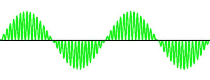
- Adjust R24 SUBC LEVEL (100k) for a suppressed carrier double sideband signal displayed on the scope. This should look sort of like a rectified AM envelope, but with the carrier appearing alternately on the positive half of the sine wave and the negative half of the sine wave. Proper adjustment is when the baseline appears straight and flat, that is, when the carrier on the positive half of the sinewave occupies all of the area under the sinewave without spilling into negative territory and the carrier on the negative half occupies all of the area above the sinewave without spilling into positive territory. Perfect adjustment may not be possible. It depends on the tolerance of the audio input summing resistors (R5, R6, R7, R8). See the waveform below.
- Remove all audio input tone/s.
- Remove the jumper across R28 (470 ohm).
- Connect a modulation monitor (or an FM stereo receiver) to the RF output (antenna output) jack of the exciter.
- Adjust R35 DEV (1k) pot for a deviation reading of +/- 7.5 kHz. (Alternately, adjust R35 until the "stereo" indicator light on the receiver just lights.) The setting of R35 should not be disturbed once it has been adjusted.
Properly Adjusted Stereo Generator - TP4 (IC1 pin 1)