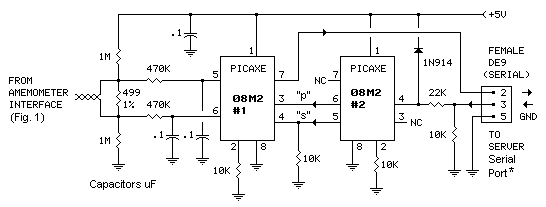
The serial interface in Figure 5 is one way to get wind speed data into your computer. It's based on the easy-to-use PICAXE microcontroller. Approximately 5 times per second, chip #1 reads the voltage drop across the shunt resistor, saves the reading and, when polled, reports to the computer via the computer's serial port (or USB port with adapter). The 499-ohm resistor produces 0.5 volt drop at 1 mA, corresponding to 50 wind speed units (MPH, m/S or km/h).
Chip #2 monitors the computer's serial port and passes poll requests to chip #1. The computer can poll for a real-time snapshot of current wind speed ("s"), or for peak/average data ("p"). The computer polls the interface at intervals determined by the host computer (the as-built system polls once every 10 minutes).
Figure 5
*Or serial/USB adapter (also called a FTDI adapter) if no serial port is available.
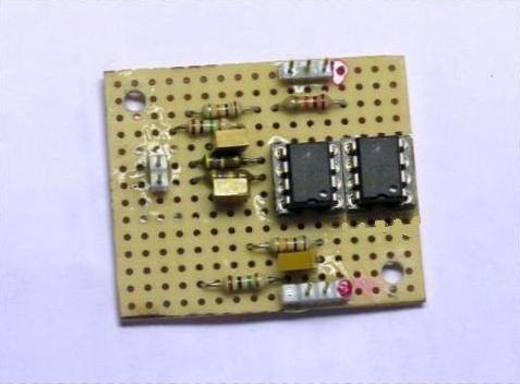
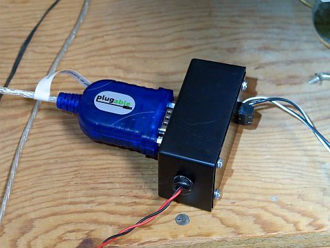
As-Built
Interface (in black box) mated with (blue) FTDI adapter
The red/black wire is 5 volt power from the computer. The black/white wire is the current loop. The silver FTDI (serial/USB adapter) cable plugs into a USB port on the computer. The adapter shows up in Device Manager as a COM port (typically COM5).
Firmware
Programs for Figure 5 PICAXE Microcontroller Interface
These chips are easily programmed - see "Programming the 08M2" box below. The programs (in Basic) are shown in blue.
Chip #1
PICAXE chip #1 continuously samples the anemometer current loop, compares each reading with previous readings (to determine peak) and totalizes the readings. Upon request from the computer, the program provides peak, total and number of samples (for computation of average), and then resets. The program will also provide an 'instantaneous' reading (one sample, no reset) if requested.
Copy and paste the code (in blue) to the PICAXE Programming Editor and program the chip:
'Code accomodates request for peak/average (p) or current wind speed (s).
'Note: "average" consists of a summation of sample readings (W5) divided by the number of samples (W7).
'The computation of average is made by the host computer (Perl code).

get_speed:

	pause 200			'200 mS, sets sample rate to ~5/sec

	ReadADC10 1, W1		'gets voltage on I/O 1 (pin 6)
					'this is one side of the shunt resistor.

	ReadADC10 2, W2		'gets voltage on I/O 2 (pin 5)
					'this is the other side of the shunt resistor

	if W1 > W2 then

	W3 = 0		'disallows polarity reversal

	else

	W3 = W2 - W1	'calculates voltage drop, this is the current "instantaneous" windspeed

	endif

	if W3 > W4  then

	W4 = W3			'peak windspeed

	endif

	W5 = W5 + W3		'accumlulates sum, sum can be up to 65535, ~600 readings at 50 MPH avg;
					'overflow carry below overcomes this limitation

	if W5 > 60000 then

	inc W6		'increments overflow carry

	W5 = W5 - 60000	'subtracts (will be added back by computer Perl program)

	endif

	inc W7			'increments sample count


	if pinc.4 = 1 then	'computer is requesting peak/average data (peak,sum,carry,count) ("p")


	SerOut 0, N2400, (#W4, 32, #W5, 32, #W6, 32, #W7, 13)	'sends data (words) to computer
					'(data, space, data, space, data, space, data, CR)


	W4 = 0			'resets words (peak)

	W5 = 0			'(sum)

	W6 = 0			'(overflow carry)

	W7 = 0			'(sample count)

	pause 50

	goto get_speed

	else if pinc.3 = 1 then	'computer is requesting current windspeed ("s")

	SerOut 0, N2400, (#W3, 13)	'sends data (word) to computer
						'data, CR (W3 = current windspeed)
						'(no reset)
	pause 87

	endif


	goto get_speed
Chip #2
The job of PICAXE chip #2 is to listen for requests from the host computer and forward the requests to chip #1.
Copy and paste the code (in blue) to the PICAXE Programming Editor and program the chip:
'Code accomodates request for current wind speed (s) or peak/average (p).

listen:


	SerIn c.3, N2400, ("c="), w1	'("c=") is qualifier, verifies the request

	if w1 = "p" then			'"p" means computer is requesting peak/average data

	high c.1				'pin 6

	elseif w1 = "s" then	'"s" means computer is requesting current ('instantaneous') windspeed

	high c.2				'pin 5

	endif

	pause 250				'250 mS, length of time outputs stay high

	low c.1				'pin 6

	low c.2				'pin 5

	goto listen
Retrieving and Processing the Data
Any number of programs written in any number of languages could be used to retrieve and process the data from the interface, so long as the program can access the computer's COM ports. The interface responds to two types of request, (1) instantaneous or (2) peak/average.
1. Instantaneous
An 'instantaneous' reading can be retrieved by sending "c=s" to the interface. The protocol is 2400/8/1/N. The interface will respond with a decimal number between 0 and 1023 that represents the difference between the two voltages at the inputs (one from each side of the shunt resistor). The number is followed by a carriage return (CR), like so: <number><CR>. The processing algorithm should multiply the number by the scale factor .488 to convert to tens of millivolts (ie, MPH or m/s). [Note: The scale factor is derived by multiplying the power supply voltage, usually 5 volts, by 100/1024.] The data can then be used in whatever manor. For example, displayed locally or passed directly to a web server for inclusion on a web page.
2. Peak/Average, Write to Files
The 'peak/average' data are retrieved by sending "c=p" to the interface. The protocol is the same, 2400/8/1/N. The interface will respond with four decimal numbers between 0 and 1023 that represent peak, sum, carry and count, separated by spaces and followed by a carriage return, like so: <peak><sp><sum><sp><carry><sp><count><CR>.
Peak:
The processing algorithm should multiply the peak number by the scale factor (.488) and write the result, followed by a space, to a file (ex, peak.txt). Write as APPEND. Truncate the file as necessary.
Average:
Average should be computed from the sum, carry and count numbers as follows:
average = [sum + (carry x 60000)] / count
The average result should then be multiplied by the scale factor (.488), followed by a space, and written to a text file (ex, average.txt). Write as APPEND. Truncate the file as necessary.